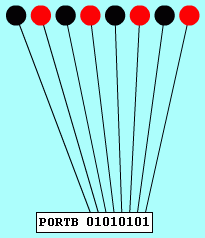
; CONNECT THE LEDs TO PORTB
MOVW 0x00
MOVWR TRISB
START:
MOVW 0x55
MOVWR PORTB
MOVW 0xAA
MOVWR PORTB
JMP START


reviseOmatic Tasks |
|
To gain access to revision questions, please sign up and log in.
a
CTRL+Click here to run the simulator.
    NOP
    NOP
    NOP
    NOP
START:
    NOP
    NOP
    NOP
    NOP
    JMP     START
Step the program and watch the PC register carefully. Answer the reviseOmatic questions on this task.
TASK:
CTRL+Click here to run the simulator.
;   CONNECT THE LEDs TO PORTB
    MOVW    0x00
    MOVWR   TRISB

START:
    MOVW    0x55
    MOVWR   PORTB

    MOVW    0xAA
    MOVWR   PORTB

    JMP     START
|
|
Step the program and watch the LEDs. Answer the reviseOmatic questions on this task.
TASK: Alter the program to repeatedly flash each LED in turn going from right to left.
cCTRL+Click here to run the simulator.
;   CONNECT TRAFFIC LIGHTS TO PORTC
    MOVW    0x00
    MOVWR   TRISC
START:
    MOVW    0x55    ; This number is wrong
    MOVWR   PORTC

    MOVW    0xA     ; This number is wrong
    MOVWR   PORTC

    MOVW    0xC     ; This number is wrong
    MOVWR   PORTC

    MOVW    0x2     ; This number is wrong
    MOVWR   PORTC

    JMP     START
|
|
Step the program and watch the traffic lights. Answer the reviseOmatic questions on this task.
TASK: Work out the correct numbers needed to control the traffic lights. Use the grid below to design the correct number sequence.

CTRL+Click here to run the simulator.
;   CONNECT THE DISPLAYS TO PORTC
    MOVW    0X00    ; SET 8 PORTC OUTPUTS
    MOVWR   TRISC   ; SET 8 PORTC OUTPUTS
    MOVWR   PORTC   ; CLEAR RIGHT SEGMENTS
    MOVW    0X80    ; CLEAR LEFT  SEGMENTS
    MOVWR   PORTC   ; CLEAR LEFT  SEGMENTS
START:
    MOVW    0X05
    MOVWR   PORTC
    MOVW    0X85
    MOVWR   PORTC

    MOVW    0X0
    MOVWR   PORTC
    MOVW    0X80
    MOVWR   PORTC

    JMP     START
|
|
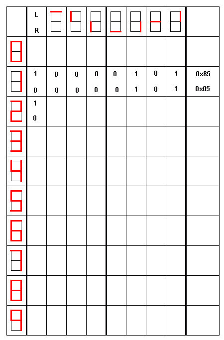
TASK: Easy: Make one of the digits count from 0 to 9.
TASK: Very Hard: Make both the digits count from 00 to 59 like the seconds and minutes on a clock.
Use this grid to help with the design of the binary control data.

CTRL+Click here to run the simulator.
; =========================================
; TRAFFIC LIGHTS WITH TIME DELAY SUBROUTINE
;       CONNECT THE LIGHTS TO PORTC
; =========================================
    MOVW    0X00    ; 0: Output  1: Input
    MOVWR   TRISC   ; PORTC 8 OUTPUTS
START:
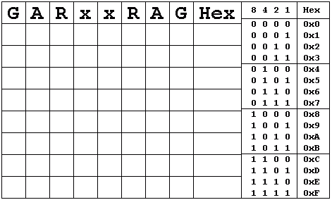
    MOVW    0X21    ; GARxxRAG - 00100001
    MOVWR   PORTC   ;   X    X
    MOVW    0X20    ; DELAY DURATION
    CALL    DELAY

    MOVW    0X62    ; GARxxRAG - 01100010
    MOVWR   PORTC   ;  XX   X
    MOVW    0X05    ; DELAY DURATION
    CALL    DELAY

    MOVW    0X84    ; GARxxRAG - 10000100
    MOVWR   PORTC   ; X    X
    MOVW    0X20    ; DELAY DURATION
    CALL    DELAY

    MOVW    0X46    ; GARxxRAG - 01000110
    MOVWR   PORTC   ;  X   XX
    MOVW    0X05    ; DELAY DURATION
    CALL    DELAY

    JMP     START
; =========================================
; ===== TIME DELAY SUBROUTINE =============
; =========================================
DELAY:
    SUBW    0X1     ; SUBTRACT ONE FROM W
    JPZ     DONE    ; JUMP IF Z FLAG IS SET
    JMP     DELAY   ; CARRY ON COUNTING
DONE:
    RET             ; SUBROUTINE RETURN
; =========================================
|
|
This example uses a SUBROUTINE. Subroutines are small, self contained, re-usable modules within a program. They are easy to code and test because each subroutine performs a single, useful well defined task. In this program, it's a time delay.
When you CALL a subroutine, the processor needs to keep track of the address it has to return to when the subroutine is finished. The Stack is used to save these Return Addresses.
The stack is an area of memory used to store the return addresses of subroutine calls. The stack pointer is a register which points to the current stack position. Data is added and removed from the stack in a strict Last In First Out (LIFO) order. The stack pointer is adjusted to keep track of these operations.
Imagine a tall pile of dinner plates. It is easy to add to the top of the pile. Also it's easy to remove from the top of the pile. Removing a middle or bottom plate is not a good idea. The plate pile is a stack and obeys the LIFO rule.
When data is added to the stack this is called a PUSH. When data is removed from the stack it's called a POP. If you write bad code, the stack can grow so big that it "eats" your program. That would be a stack overflow. If you write your code correctly, each CALL has a matching RETurn. If you have more calls than returns, your stack will grow and eat your program. If you have more returns than calls, you will get a Stack Underflow. This might not destroy your program but something is going to break.
The Task ...
In this example switches are used to control the motor in an H Bridge configuration.
CTRL+Click here to run the simulator.
; =======================================
;    H  Bridge  Motor  Control
;    CONNECT  HBRIDGE TO PORTB
;    CONNECT SWITCHES TO PORTB
; =======================================
    MOVW    0XF0    ; 4 Inputs & Outputs
    MOVWR   TRISB   ; Set PORTB direction
START:
    MOVRW   PORTB   ; READ PORTB
    ANDW    0X70    ; BIT MASK
    SUBW    0X10    ; TEST S4 CLOSED
    JPZ     FORWARD ; Jump If Closed

    JMP     COAST   ; Freewheel
; =======================================
FORWARD:
    MOVW    0X09    ; Close bits 0 and 3
    MOVWR   PORTB
    JMP     START
; =======================================
COAST:
    MOVW    0X0     ; Open all switches
    MOVWR   PORTB
    JMP     START
; =======================================
|
|
The Code
TASK: Add to this example.
CTRL+Click here to run the simulator.
START:
; =========================================
;       Initialise PRE and TMR
; =========================================
    MOVW    0X1     ; Copy 1 into ...
    MOVWR   PRE     ; ... the prescaler
    MOVW    0X08    ; Copy 8 into ...
    MOVWR   TMR     ; ... the timer

; =========================================
;       Poll the TMR flag (T)
; =========================================
POLL:
    MOVRW   SR      ; Copy SR into W
    ANDW    0x02    ; Bit mask
    JPZ     POLL

; ==========================================
; == This code runs when TMR reaches zero ==
; ==========================================
    NOP
    NOP
    NOP
    NOP
    JMP     START
; ==========================================
TASK: Copy and paste this code into the simulator and run the program.

CTRL+Click here to run the simulator.
; ================================
; ===== GRAY CODE CONTROLLER =====
; ===== CONNECT TO PORTC =========
; ================================
    MOVW    0X3F
    MOVWR   TRISC
FORWARD:
    MOVW    0X40    ; Set bit 6
    MOVWR   PORTC
F_REP:
    MOVRW   PORTC
    ANDW    0X3F
    SUBW    0X0F
    JPZ     BACKWARD
    JMP     F_REP

BACKWARD:
    MOVW    0X80    ; Set bit 7
    MOVWR   PORTC
B_REP:
    MOVRW   PORTC
    ANDW    0X3F
    SUBW    0X03
    JPZ     FORWARD
    JMP     B_REP
TASK:
CTRL+Click here to run the simulator.
; ================================
; === CONNECT STEPPER TO PORTB ===
; ================================
start:
    movw    0x1
    movwr   portb
    nop
    nop

    movw    0x2
    movwr   portb
    nop
    nop

    movw    0x4
    movwr   portb
    nop
    nop

    movw    0x8
    movwr   portb

    jmp     start
|
|
TASK:
CTRL+Click here to run the simulator.
; ============================
; === CONNECT DAC TO PORTA ===
; ============================
    movw    0x0
start:
    movwr   porta
    addw    0x1
    jmp     start
TASK:
|
|
CTRL+Click here to run the simulator.
; =================================
; === CONNECT RAMP ADC TO PORTA ===
; =================================
    jmp init
; ===== VARIABLES =====
count:  db  0x00
delay:  db  0x30
mask:   db  0x80
; =====================
init:
    movrw   mask
    movwr   trisa
    movw    0x0
    movwr   count
s:
    movrw   count
    movwr   porta
    movrw   porta
    andw    0x80
    jpz     pause
    inc     count
    jmp     s

pause:
    movrw    delay
rep:
    subw    0x1
    jpz     init
    jmp     rep
|
|
TASK:
reviseOmatic V3 Contacts, ©, Cookies, Data Protection and Disclaimers Hosted at linode.com, London