MOSFET Switches - Frequently Used
MOSFETs enable a small voltage and an extremely small current to control a much larger current up to several amps for a power MOSFET.
- Very high (near infinite) input resistance.
- Very fast switching.
- Low output resistance.
- Able to switch large currents (up to nine amps with a power MOSFET and a heat sink).
- Zero volts on the gate will turn the switch off.
- Two to five Volts on the gate (depending on the MOSFET) are needed to saturate the MOSFET (turn it on fully).
- Low drain voltage when saturated (0.1 Volts).
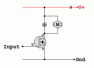
MOSFET Switching Circuit

For the Falstad Circuit Simulation, CTRL+Click MOSFET LED Switch Simulation
In options, check European Resistors and uncheck Conventional Current.
Click the switch to turn it on or off.
Alternatively view MOSFET_Switch.txt.
Save or copy the text on the web page. Import the saved or copied text into the Falstad simulator.
Here is the new HTML5 Simulator Site.
For the Falstad Circuit Simulation, CTRL+Click MOSFET Motor Back EMF Simulation
In options, check European Resistors and uncheck Conventional Current.
Click the switch to turn it on or off.
Alternatively view MOSFET_Switch_Back_EMF.txt.
Save or copy the text on the web page. Import the saved or copied text into the Falstad simulator.
Here is the new HTML5 Simulator Site.
Back EMF
- The diode is needed if the load is inductive.
- The diode protects the MOSFET from high voltage back emf pulses by allowing the load current to die away gradually.
MOSFET Simulation
Run this MOSFET Simulation.
Thermal Stability
- When a MOSFET heats up, its gain decreases.
- This causes the current to decrease.
- This makes it cooler so thermal runaway is less likely.
MOSFETs and Relays
- MOSFETS are more reliable - no moving parts.
- Relays can switch higher voltages.
- Relays can switch AC - MOSFETs can not.
Bipolar Junction Transistor Switches - OK for Low Power
Current Gain
- Current Gain = Ic / Ib Values from 10 to 500 are common.
A small base current is used to switch a much larger collector current.
- Also known as a common emitter switch.
- Bipolar junction transistors (BJTs) can be used as a Switch or Transducer Driver.
- Many transducers need quite a lot of current to operate.
- This transducer driver circuit amplifies the small base current from a low power circuit and provides enough current to operate the transducer.
- If the load is inductive, the diode is needed to protect the transistor from "Back EMF" damage. It works by allowing the inductor current to die away gradually when the transistor is suddenly switched off.
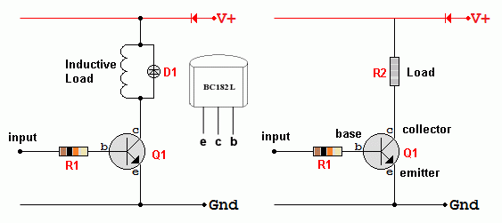
Bipolar Transistor Used as a Switch

- R1 limits the base current to a few milliamps
- Q1 is an NPN transistor. For example a BC182L with a current gain of about 300
- R2 is the load. This could be a bulb, an LED, a relay, a small motor, a buzzer and so on.
- D1 is only needed if the load is inductive. Inductive loads are electromagnetic devices such as motors, relays and some buzzers. When the current through an inductor is turned off suddenly, a large Back EMF is produced. This could be enough to destroy the transistor. By adding the diode, the current through the inductor can die away gradually (by flowing through the diode). This prevents the large back EMF.
- When the transistor is saturated (fully turned on), Vbe = 0.7V (the base emitter voltage)
- When the transistor is saturated (fully turned on), Vce = 0.2V (the collector emitter voltage)
- When the transistor is saturated (fully turned on), the collector current depends only on the load resistance and the power supply voltage.
- When the transistor is cut off (fully turned off), Vce = Vs.
Try this Flash simulation.
Alternative Circuits
- Use a MOSFET. This switches faster. Bigger currents can be handled. A minute input power is needed to operate the switch. The MOSFET is voltage operated. This is often an advantage.
- Use a relay. This is mechanical, slow and relatively unreliable but enormous currents can be switched.
- Use a thyristor or a triac. These are not on the AQA specification so you will need to find the details elsewhere.
Estimating Component Values
Here is an example ...
- The load resistance is 600 Ω
- The load current is 20mA.
- The transistor current gain is at least 200.
- To get 20mA in the collector, 20/200 mA base current is needed = 0.1 mA
- In the 12 Volt circuit above, the base resistor connected to 12V would need to be ...
- R = V / I
- R = 12 / 10-4 = 120 kΩ A 100 kΩ resistor would be OK.
- You should now notice that the base resistor is 200 times the load resistor because the current gain is 200. This gives a quick way to estimate what base resistor to use.
Thermal Stability
- When a bipolar transistor heats up, its current gain increases.
- This causes the current to increase.
- This makes it hotter.
- In a poorly designed circuit, this is a vicious cycle and can lead to thermal run-away and the destruction of the transistor.
- NEGATIVE FEEDBACK help to solve the problem.
- Increasing current is used to shut down the device, returning the current back to a safe level.


