Light Emitting Diodes |
|
To gain access to revision questions, please sign up and log in.
In the circuit below, the resistor limits the current through the LED to a safe level. A typical LED current is 10mA.
This circuit has a 5 Volt supply. There are 2 Volts across the LED. The remaining 3 Volts are across the resistor. Using Ohm's law ...
Allowing a small safety margin, the E24 330R was chosen allowing just under 10mA to flow.
d
This circuit has a 5 Volt supply. There are 2 Volts across the LED. The remaining 3 Volts are across the resistor.
This circuit has a 5 Volt supply. There are 2 Volts across the LED.
This circuit has a 5 Volt supply.
The graph below shows the approximate characteristics of an LED.
The reverse leakage current has been exaggerated to make it show on the graph.
The reverse breakdown voltage is quite low (5 volts approx).
It's easy to destroy LEDs. Too much forward current or too much reverse voltage will do the job.
This uses Gallium arsenide instead of Silicon as the semiconductor material.
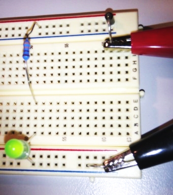
Circuit diagram and Layout for an LED Power Indicator ...
For the Falstad Circuit Simulation, CTRL+Click LED Circuit
In options, check European Resistors and uncheck Conventional Current.
Alternatively view LED.txt.
Save or copy the text on the web page. Import the saved or copied text into the Falstad simulator.
Here is the new HTML5 Simulator Site.
Measure ...
Infra-Red photons have a low energy. Ultra-Violet photons have a much higher energy. The photon energy is proportional to the LED voltage.
| Colour | Approximate Voltage Drop | Photon Energy | Photon Wavelength |
| Infrared | 1.6 V | Lowest | Longest |
| Red | 1.8 V to 2.1 V | ||
| Orange | 2.2 V | ||
| Yellow | 2.4 V | ||
| Green | 2.6 V | ||
| Blue | 3.0 V to 3.5 V | ||
| White | 3.0 V to 3.5 V | ||
| Ultraviolet | 3.5 V | Highest | Shortest |
For the Falstad Circuit Simulation, CTRL+Click LEDs in Parallel - Bad Idea
In options, check European Resistors and uncheck Conventional Current.
Turn on between one and five LEDs and watch how bright they are.
Alternatively view LED_Parallel.txt.
Save or copy the text on the web page. Import the saved or copied text into the Falstad simulator.
Here is the new HTML5 Simulator Site.
This is a bad idea. The current limiting resistor sets the total current which is shared between the LEDs. The same fixed current is split between how ever many LEDs are turned on. One LED might hog the current because the warmest LED will carry the most current so it also stays the warmest. The voltage across LEDs is about two volts. This stays the same if several LEDs are connected in parallel. Connecting a fourth LED in parallel does not increase the total current. It just makes all the LEDs dimmer because the same current is shared between more LEDs.
lLEDs in series work just fine unless there are too many and the power supply voltage is no longer sufficient.
R = V / I = (12 - 2 - 2 - 2) / 0.01 = 600Ω Using 560Ω the LED current is 10.7mA. This is safe.
reviseOmatic V3 Contacts, ©, Cookies, Data Protection and Disclaimers Hosted at linode.com, London