
RF Amplifier |
|
To gain access to revision questions, please sign up and log in.

L1 |
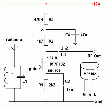
This inductor could consist of a ferrite rod with a pre-wound coil. For higher frequencies, it could be an air spaced coil. Together with C1 it forms a tuned circuit. The coil also grounds the FET gate for DC voltages but not for RF voltages. |
C1 |
This variable capacitor is used with L1 to make a tuned circuit used to select the desired frequency. |
Antenna |
This could be half a wavelength long at the desired receiving frequency. A shorter wire will often work well enough. |
R1 |
The current through the FET produces a potential across R1. This potential is held constant by the decoupling capacitor C2. This potential biases the FET so a suitable current flows through it. |
C2 |
This decoupling capacitor ensures that the potential on the source of the FET is held constant. There should not be any radio frequency or other alternating voltages here. |
R2 |
When the current through the FET changes, the potential difference across R2 changes. Point X in the circuit is held at a constant potential by C4. Therefore the drain voltage varies when the FET current changes. This is the amplifier output signal. |
FET |
Small changes in gate potential cause much larger changes in the current flowing through the FET. |
R3 & C4 |
C4 decouples the amplifier. AC or RF power supply line fluctuations do not reach the amplifier and amplifier signals do not reach the power supply line. This ensures that the power supply can not accidentally act as a signal path. |
C3 |
C3 is a coupling capacitor. It couples the RF output signal to the next receiver stage. At the same time, it blocks DC voltages. |
reviseOmatic V3 Contacts, ©, Cookies, Data Protection and Disclaimers Hosted at linode.com, London