PIC16F88 0E Servo PWM |
|
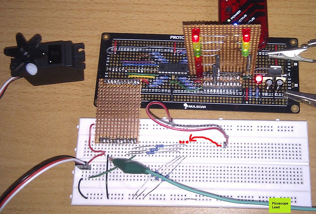
The red jump lead in the photo is used to simulate the push button switches by prodding the points labelled with red dots.
The green lead goes to the oscilloscope to measure the control signals to the servo.
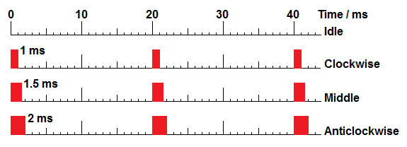
Servos are controlled by a stream of pulses. The pulse width determines the servo position. This typical servo rotates about 90 degrees.
The PIC16F88 has built-in hardware for generating pulses. There's a bit of a learning curve to get up to speed with this PIC subsystem so we'll use Timer0 instead.
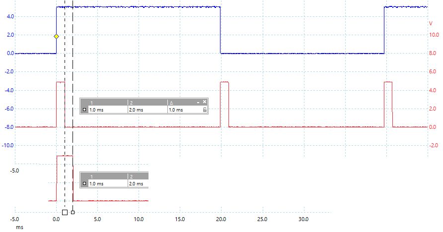
Every 20 ms, a Timer0 interrupt will trigger the interrupt subroutine.
;*******************************************************************************
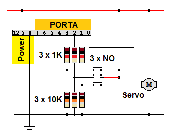
; INPUT: Three push buttons.
; One to increase the pulse duration (go anticlockwise)
; One to decrease the pulse duration (go clockwise)
; One to turn on the pulses so the servo acts.
; PROCESS: During the timer interrupt, poll the switches.
; Increase or decrease the pulse width depending on the switches.
; Turn on the pulse stream if that switch has been pressed.
; OUTPUT: Servo signals.
; Every 20 ms send pulses to the servo.
; The pulses will be between 1 and 2 ms duration.
; Copy PulseWidth to PORTB - LEDs show the value (for debugging)
;*******************************************************************************
; PIC16F88 Configuration Bit Settings
;*******************************************************************************
#include "p16F88.inc"
; CONFIG1 - Internal oscillator - Want I/O - Everything else turned off
__CONFIG _CONFIG1, _FOSC_INTOSCIO & _WDTE_OFF & _PWRTE_OFF & _MCLRE_OFF & _BOREN_OFF & _LVP_OFF & _CPD_OFF & _WRT_OFF & _CCPMX_RB0 & _CP_OFF
; CONFIG2 - Turn on both
__CONFIG _CONFIG2, _FCMEN_ON & _IESO_ON
;*******************************************************************************
; Uninitialised Data - Reserve bytes here ...
;*******************************************************************************
UDATA
PulseWidth RES 1 ; Allow numbers between 0 and 199 to control the pulse width.
PortaValue RES 1 ; Save the PORTA value for later processing
DelayCount RES 1 ; Time delay counter
;*******************************************************************************
; RESET VECTOR
;*******************************************************************************
RES_VECT CODE 0x0000 ; processor reset vector
GOTO CODE_INIT ; beginning of program, initialise stuff
;*******************************************************************************
; INTERRUPT HANDLING
;*******************************************************************************
ISR CODE 0x0004 ; The interrupt vector location is always 0x0004
GOTO ISR_HANDLER ; Jump to the Interrupt handling code
;*******************************************************************************
; MAIN PROGRAM
;*******************************************************************************
MAIN_PROG CODE ; let linker place main program
CODE_INIT: ; INITIALISATION
CALL CLOCK_INIT ; Set up the Clock Frequency
CALL VAR_INIT ; Initialise variables
CALL PORT_INIT ; Set up I/O Ports
CALL TIMER_INIT ; Set up Timer0
CALL TIMER_START ; Start the Timer
GOTO IDLE_LOOP ; Snooze in the Idle Loop
;*******************************************************************************
; INTERRUPT SUBROUTINE
; This ought to save and restore the context
; It's not secessary in this simple example
;*******************************************************************************
ISR_HANDLER:
CALL TIMER_START ; Start the Timer
MOVLW 0x80 ; 1000 0000 to invert RA7
XORWF PORTA, F ; Invert RA7 by XORing - Oscilloscope signal
MOVF PORTA, W ; Copy PORTA into WREG
MOVWF PortaValue ; Can't do bit tests directly on WREG
BTFSC PortaValue, RA1 ; Test RA1 - Skip next line if RA1 is LOW.
CALL IncPulseWidth ; Increase the pulse width.
BTFSC PortaValue, RA2 ; Test RA2 - Skip next line if RA2 is LOW.
CALL SendServoPulse ; Increase the pulse width.
BTFSC PortaValue, RA3 ; Test RA3 - Skip next line if RA1 is LOW.
CALL DecPulseWidth ; Decrease the pulse width.
MOVF PulseWidth, W ; Copy PulseWidth to WREG
MOVWF PORTB ; Copy WREG to PORTB - LEDs show the PulseWidth
RETFIE ; Return from interrupt
;*******************************************************************************
; INITIALISE PORTS
;*******************************************************************************
PORT_INIT:
BANKSEL TRISA ; Set RP0 in STATUS to select bank 1.
MOVLW b'00000000' ; Disable ADC / Set for digital i/o (not analogue)
MOVWF ADCON1 ; Disble ADC module (Never leave this to chance)
MOVWF ANSEL ; Turn off analog i/o. Select digital i/o (Never leave this to chance)
MOVWF TRISB ; Set PORTB as outputs
MOVLW b'00101110' ; 0, 4, 6 and 7 are outputs. The rest are inputs.
MOVWF TRISA ; Set porta as outputs - RA5 is input only so this bit is ignored
RETURN
;*******************************************************************************
; INITIALISE CLOCK FREQUENCY - 4MHz - 1 microsecond per instruction
;*******************************************************************************
CLOCK_INIT:
BANKSEL OSCCON
movlw b'01100000' ; -110---- 4 MHz
movwf OSCCON ; At 4 MHz it's one microsecond per line of code.
RETURN
;*******************************************************************************
; INITIALISE TIMER0
;*******************************************************************************
TIMER_INIT:
BANKSEL OPTION_REG ; Set RP0 in STATUS to select memory bank 1.
CLRWDT ; Clear the Watchdog Timer and prescaler
MOVLW b'00000111' ; 1:256 TMR0 rate prescaling
;MOVLW b'00000001' ; 1:4 TMR0 rate prescaling - for use in the simulator
MOVWF OPTION_REG ; The prescaler settings are stored in OPTION_REG
BSF INTCON, GIE ; Turn on interupts globally
BSF INTCON, TMR0IE ; Turn on Timer0 interupts
RETURN
;*******************************************************************************
; START TIMER - Times 20 ms
; Prescaler is set to 1:256
; Count from 178 to 256 (78 steps) each taking 256 microseconds =~ 19.97 ms
;*******************************************************************************
TIMER_START:
BANKSEL TMR0 ; Clear RP0 in STATUS to select memory bank 0.
BCF INTCON, TMR0IF ; Clear the TMR0IF flag
MOVLW d'178' ; TMR0 counts from 178 to 256
;MOVLW d'248' ; TMR0 counts from 178 to 256 - for use in the simulator
MOVWF TMR0 ; 178 copied into TMR0
RETURN
;*******************************************************************************
; Set PulseWidth to zero
;*******************************************************************************
VAR_INIT:
MOVLW 0x00
MOVWF PulseWidth
RETURN
;*******************************************************************************
; Add one to the PulseWidth up to a maximum of 200
;*******************************************************************************
IncPulseWidth:
INCF PulseWidth, F ; Add one to PulseWidth
MOVLW d'201' ; See if it's gone over 200
SUBWF PulseWidth, W ; If PulseWidth is 201 then the Z flag will be set
BTFSC STATUS, Z ; Test the Zero flag in the STATUS register
DECF PulseWidth ; If set, reduce PulseWidth from 201 back to 200
RETURN
;*******************************************************************************
; Subtract one from the PulseWidth down to a minimum of one
;*******************************************************************************
DecPulseWidth:
DECF PulseWidth, F ; Subtrct one from PulseWidth
BTFSC STATUS, Z ; Test the Zero flag in the STATUS register
INCF PulseWidth ; If set, add one to the PulseWidth from 0 back to 1
RETURN
;*******************************************************************************
; Send a pulse to the servo
; The pulse width is 1 ms plus PulseWidth / 200 ms
;*******************************************************************************
SendServoPulse:
BSF PORTA, RA0 ; Start the servo pulse
MOVLW d'197' ; Should be 200 but reduced to 197 because of time to call, return etc.
CALL MyDelay ; A fixed width 1 ms duration
MOVF PulseWidth, W ; ADDED TO
CALL MyDelay ; the value stored in PulseWidth
BCF PORTA, RA0 ; End the servo pulse
RETURN
;*******************************************************************************
; Time delay from 1000 to 2000 microseconds
; 200 in WREG will give a 1 millisecond delay ignoring call and return overheads
;*******************************************************************************
MyDelay:
MOVWF DelayCount
DelLoop:
NOP ; 1 microsecond
NOP ; 1
DECFSZ DelayCount, F ; 1
GOTO DelLoop ; 2 Total = 5 x 200 = 1 millisecond
RETURN
;*******************************************************************************
; The Idle Loop
; MS Windows has an "idle process" which waits for the user to do something.
;*******************************************************************************
IDLE_LOOP:
NOP
NOP ; NOPs make code execution visible
NOP
NOP
GOTO IDLE_LOOP
END
Contact, Copyright, Cookies and Legalities: C Neil Bauers - reviseOmatic V4 - © 2016/17
Hosted at linode.com - London
Please report website problems to Neil