Truth Tables |
|
To gain access to revision questions, please sign up and log in.
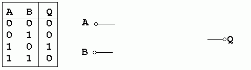
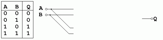
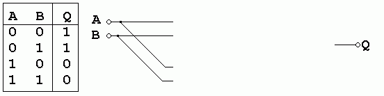
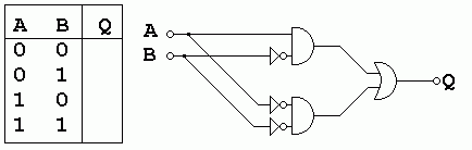
AND OR NAND NOR XOR NOT
  AND          OR           NAND         NOR          XOR          NOT
  A B  Q       A B  Q       A B  Q       A B  Q       A B  Q       A  Q
  0 0          0 0          0 0          0 0          0 0          0
  0 1          0 1          0 1          0 1          0 1          1
  1 0          1 0          1 0          1 0          1 0
  1 1          1 1          1 1          1 1          1 1
reviseOmatic V3 Contacts, ©, Cookies, Data Protection and Disclaimers Hosted at linode.com, London