Modulo N Counter |
|
To gain access to revision questions, please sign up and log in.
a
On the rising edge of the clock pulse, D is copied to Q.
Since NOT Q is connected to D, the data is inverted on each rising edge.
This has the effect of dividing the frequency by two.
b
This divides the frequency by 8 (or by two three times).
On the rising edge of the clock pulse the counter output increases by one.
The output from the left flip-flop is worth one (least significant bit LSB).
The output from the middle flip-flop is worth two.
The output from the right flip-flop is worth 4 (most significant bit MSB).
Here is a timing diagram for the three bit counter.
This is a counter that resets at a chosen number. For example a two digit decimal counter, left to its own devices will count from 00 to 99. This is not much use for a clock unless you have 100 second minutes. To fix the problem, the counter must go from 00 to 59. This is achieved by detecting a 6 in the left hand digit and using it to reset the counter to zero. This would be a Modulo 6 Counter or 60 if you included both digits.
d
The circuit above detects a six or 0110 in binary. You could use the fool proof circuit but in fact the simpler circuit works too because the 0110 pattern only occurs once between 0 and 9 in decimal numbers. The output is used to reset the counter.
Here is a timing diagram for the modulo 6 counter. It shows the count going from 0 to 5 in regular time steps. The counter reaches 6 but only for about a microsecond before it resets to zero.
For the Falstad Circuit Simulation, CTRL+Click Modulo 10 Counter
In options, check European Resistors and uncheck Conventional Current.
Alternatively view Modulo_10_Counter.txt.
Save or copy the text on the web page. Import the saved or copied text into the Falstad simulator.
Here is the new HTML5 Simulator Site.
Click the thumbnail for a full-size image. You might want to print this.
The reset circuit has not been connected in this diagram. It is your task to work out how to set it up. Print the image above and use it as a guide. The wiring gets quite crowded so neatness is essential. Try colour coding your wiring. In this diagram red is for the + supply, green is for the counters, blue is for the led wiring and black is for ground connections. Choose your own colour for the reset circuit.
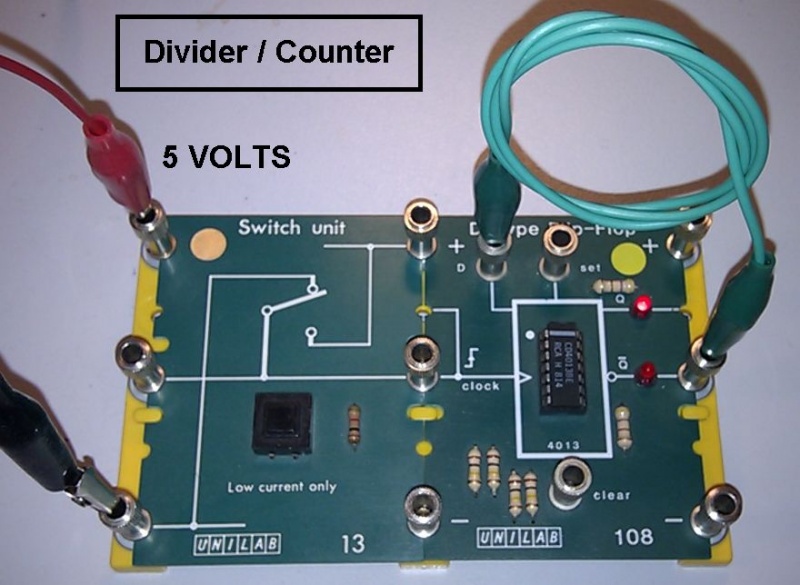
The 7474 D Type Flip Flop differs from the usual one in AQA exam questions. The AQA version has set and reset pins. This real-life chip has set and reset pins. The 4013 CMOS chip is just like the one in the AQA exam questions.
gThis circuit, as expected, completely fails to count correctly. This is due to SWITCH BOUNCE.
To fix the problem, use a de-bounced switch instead.
reviseOmatic V3 Contacts, ©, Cookies, Data Protection and Disclaimers Hosted at linode.com, London