
RANDOM PAGE
SITE SEARCH
LOG
IN
SIGN UP
HELP
To gain access to revision questions, please sign up and log in.
Everyone
aCapacitor Construction
Two parallel plates insulated from each other. Many capacitors have this structure rolled up into a tube to save space.
bCapacitor Symbols and Images
 |
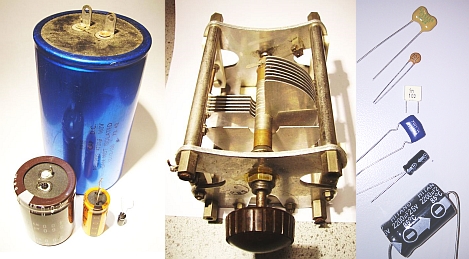
Left to right ...
- Electrolytic - Connect the right way round to prevent explosion!
- Tuning - A variable capacitor used for tuning a radio transmitter.
- Small capacitors including two electrolytics. Look for the arrows with the minus signs.
|
cCapacitor Simulations
Click the switch to alternate between charging and discharging.
This animation has correct physics so it could be used to plot a realistic capacitor charging graph.
|
On the animation page, click the Fill/Empty button to alternate between filling and emptying.
- It takes time to fill the tank / charge the capacitor
- The tank/capacitor fills fast at first and the fill rate slows down, the fuller it gets
- The tank/capacitor empties fast at first and the emptying rate slows down, the emptier it gets
- Eventually the battery/reservoir would be drained
- The water level/capacitor charge can not change suddenly
- If there were more pressure/voltage, the tank/capacitor would fill faster
- The tank fills until the water levels are equal. The capacitor charges until the voltages are equal.
|
dCapacitor Properties
The main characteristics or properties of capacitors are ...
- Capacitance is measured in Farads or more often pico, nano or microfarads.
- One Farad is an enormous capacitance and rarely found in real life.
- Capacitors store energy in the form of a stored electric charge.
- Charge is measured in Coulombs.
- Energy is measured in Joules.
- Q = CV where
- Q is the charge,
- C is the capacitance and
- V is the potential difference across the capacitor
- If you double the voltage, the stored charge will double.
- E = CV2 / 2 where
- E is the energy stored,
- C is the capacitance and
- V is the potential difference across the capacitor
- If you double the voltage, the energy stored increases by 22 (four times)
More details ...
- capacitors block direct current (DC)
- capacitors pass alternating current (AC)
- The breakdown voltage (in Volts). The voltage across the capacitor should never exceed this.
- The upper useful frequency properties.
- The DC leakage current (a particular problem with electrolytic capacitors).
YouTube Video: VERY Big Capacitor vs Watermelon
eCapacitor Uses
In your project report, you have to describe how your circuit works. If your circuit contains a capacitor, one or more of the following explanations should be useful.
fTiming Capacitor
|
- R C timing circuits use a resistor and a capacitor for timing purposes.
- The capacitor charges through the resistor.
- A bigger resistor will make the capacitor take longer to charge.
- Also a bigger capacitor will take longer to charge.
|
gCoupling Capacitor
|
- Also known as a DC blocking capacitor.
- Couple an AC signal from one subsystem to the next.
- Prevent DC potentials from being coupled from one subsystem to the next.
|
hDecoupling Capacitor
|
- Remove unwanted AC signals from the circuit.
- The capacitor is connected to ground and any AC signals are passed straight to ground.
|
iSmoothing Capacitor
|
- DC power supplies produce lumpy DC.
- The smoothing capacitor stores enough charge to smooth out the lumps.
- Smoothing capacitors are often very big.
|
jFrequency Filtering Capacitor
|
- This is an A2 topic but many AS projects need to take this into consideration.
- Since capacitors pass high frequencies and block low ones and DC, they can be used to filter low or high frequencies.
- Capacitors can be wired up to couple (pass) or decouple (block) higher frequencies.
|
kTuning Capacitor
|
- When combined with an inductor, a tuned circuit is formed.
- This is used in radio tuning to select the wanted signal and reject others.
|
lElectrolytic and Tantalum Capacitors
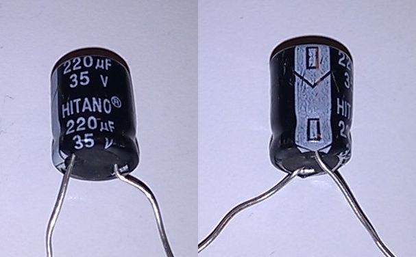
Electrolytic capacitors use thin rolled up foil plates separated by a liquid or gel electrolyte. The insulation between the plates relies on a chemical reaction. If the capacitor is connected up the wrong way round, this chemistry fails and the capacitor works as a conductor instead. It gets hot and can explode!
- The negative pin is indicated by the arrows and minus signs.
- Electrolytic capacitors have a very large capacitance for their size.
- The working voltage is low. 12 to 160 volt ratings are common. The image above shows a 35 Volt capacitor.
- They have a significant DC leakage current, sufficient to upset some timing circuits
- They are not manufactured with good tolerance / accuracy and this can be up to 50% out
- Their capacitance is not stable and can change with time
- They are not suitable for high frequency radio applications because the coiled up foil roll acts as an inductor blocking high frequency performance
- They work well at audio and ultrasonic frequencies.
Their uses include ...
- DC power supply smoothing - This is a particular example of decoupling.
- Audio signal coupling - Block DC and pass AC.
- Audio signal decoupling - Remove unwanted AC signals.
- Timing in 555 or other timer circuits - RC resistor capacitor circuit
They can not be used ...
- In AC circuits where the polarity across the capacitor reverses
- In logic gate astable circuits because the polarity across the capacitor reverses
mCapacitor Labelling
| Big Capacitors |
These have the value printed in plain language like 4700 µF and there is no problem.
|
| Tiny Capacitors |
Tiny capacitors might be labelled with a number up to three digits long. These are values in picofarads (puffs) and the third digit (if present) is the number of zeros you need to add. If there is a letter, this is the capacitor tolerance (accuracy of manufacture). J = 5%. K = 10%. M = 20%. Google for the other tolerance codes if you need them.
Examples:
- 8 = 8 picofarads
- 22 = 22 picofarads
- 121 = 120 picofarads (add one zero)
- 332 = 3300 picofarads (add two zeros)
- 473 = 47000 picofarads or 47 nanofarads (add three zeros)
|
| Working Voltage |
On big capacitors, this is clearly labelled. On tiny capacitors it might not be labelled at all. Usually small capacitors will be safe in any AQA project circuit because they have a high enough voltage rating. Electrolytic capacitors are more of a problem. You must take care that the voltage rating is higher than any voltage the capacitor will experience at any time in your circuit. It is a good idea to allow a safety margin so use a 16 Volt capacitor in a 12 Volt circuit. High voltage capacitors tend to be physically large so, if possible, it is a good idea to design circuits to work on lower voltages. Alternatively design circuits that avoid the use of capacitors.
|
nA2 ONLY: Current Voltage Phase Relationship
- Current leads the voltage across the capacitor (is phase shifted by 90o).
- Using a water analogy, the current is the water flow and the voltage is how full the bucket is.
- If you tip water into a bucket, there is a large water flow but it still takes time to fill the bucket.
- Once the bucket is full, the water flow stops. Capacitors are the same.
- A current is needed to charge the capacitor. Initially, the current flows while the voltage is still zero or low.
- Once the capacitor is charged, the current flow drops to zero and the voltage reaches its maximum.
- So current leads the voltage.
reviseOmatic V3
Contacts, ©, Cookies, Data Protection and Disclaimers
Hosted at linode.com, London