
RANDOM PAGE
SITE SEARCH
LOG
IN
SIGN UP
HELP
To gain access to revision questions, please sign up and log in.
Everyone
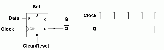
- On the rising edge of the clock pulse, the input D is copied to the output Q.
The data is stored until the next rising edge.
At any time, the chip can be SET or RESET with a HIGH pulse on S or R.
- This is called edge triggered. If the DATA input changes between clock pulses, this has no effect on the output.
- The rising edge of the clock pulse stores the input bit so this flip flop can be used as a data latch (memory).
- A single D Type Flip Flop can store one bit.
- On the rising edge of the clock pulse,
if D = 1 the circuit is "SET and Q goes high
if D = 0 the circuit is "RESET" and Q goes low.
Not Q is always in the opposite state to Q.
Here is the symbol of a D Type Flip Flop.
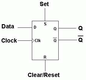
- The device can be set or reset at any time by setting the S or R inputs high.
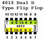
- This applies to AQA exam questions and 4000 series gates.
- If you use 74xxx gates in your project, these come with Set and Reset inputs where low signals are needed.
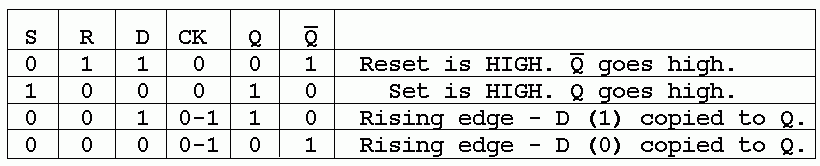
Data Latch
- On the rising edge of the clock pulse, the data on D0, D1, D2 and D3 is copied to Q0, Q1, Q2 and Q3.
- Data latches are needed to store data that is only available or valid for a short time.
- For example data from the parallel port may not be valid for long.
- If this data is latched (stored), the latch output remains available for as long as necessary.
- The data remains valid until the next clock pulse.
Frequency Divider
On the rising edge of the clock pulse, D is copied to Q.
Since NOT Q is connected to D, the data is inverted on each rising edge.
This has the effect of dividing the frequency by two.
- The D Type Flip Flop is used in Binary Counters.
- Here is the circuit for a one bit counter.
- This can also be used as a frequency divider. It divides the frequency by two.
- The UP in Up Counter is because the counter counts normally with increasing numbers like 0, 1, 2, 3 etc.
- The output of this circuit is high for 50% of the time and low for 50% of the time.
- This is a 1:1 mark space ratio.
- This is true whatever the mark space ratio of the clock pulses.
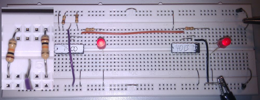
Switch Debounce and a One Bit Counter - Build This
The two NAND gates are connected as a Bistable Flip Flop. This is used to debounce the switch pulses. The 4013 D Type Flip Flop is wired as a one bit binary counter. Each time the Bistable LED comes on (the rising edge), the counter LED changes state. This counter counts 0, 1, 0, 1, Etc.
For the Falstad Circuit Simulation, CTRL+Click One Bit Counter
In options, check European Resistors and uncheck Conventional Current.
Click the switch to clock the counter.
Alternatively view One_Bit_Counter.txt.
Save or copy the text on the web page. Import the saved or copied text into the Falstad simulator.
Here is the new HTML5 Simulator Site.
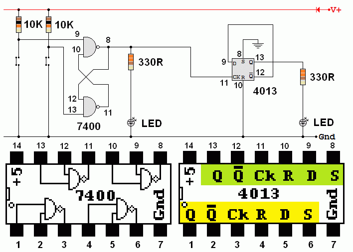
This is a slightly odd circuit because two different families of logic chips are being used.
- The 74xx series chips run on 4.75 to 5.25 Volts and consume more power.
- The 40xx series chips are less fussy about the power supply voltage and they consume less power.
- The 7400 could be replaced with a 4011 chip but the pinout is not the same so some re-wiring would also be needed.
A Two Bit Counter - Build this if you have time.
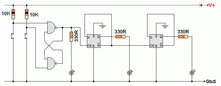
- This circuit adds a second stage to the counter. The two stages now count 0, 1, 2, 3, 0, 1, 2, 3, Etc.
- Every time a new stage is added, the count upper limit doubles. 1, 3, 7, 15, 31, 63 Etc.
- A seven stage counter counts up to 2N - 1 = 27 - 1 = 127
reviseOmatic V3
Contacts, ©, Cookies, Data Protection and Disclaimers
Hosted at linode.com, London