WANTED: Individual or team to take over this project. I'm in my 70's and want to put my feet up. Contact details in footer.
| GCSE Control Systems >Bread Maker< |
Control Systems Bread Maker |
|
This is an example of a more complex control system containing several subsystems. After long and faithful service this bread maker finally wore out. The electronics were still working well but the moving parts had completely worn out. Here is am approximate system diagram.
This images below show the machine after dismantling. This machine was built quite a long time ago. A similar machine today might contain far fewer components. This is because microcontrollers have improved and more of the required functions are built onto this single chip. The high voltage power switching would not have changed much.
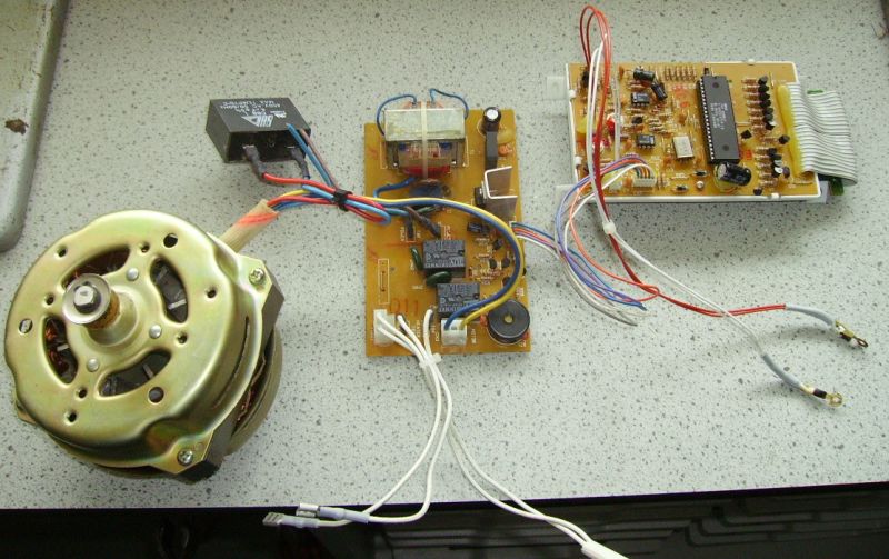
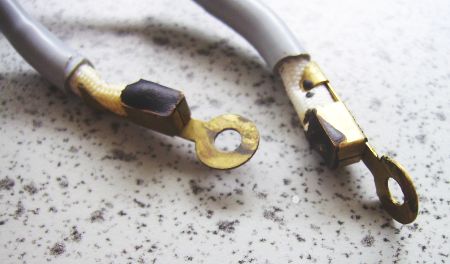
The temperature sensors control the cooking temperature and also the dough rising temperature. They are thermistors and they were bolted onto the machine very close to the bread pan.
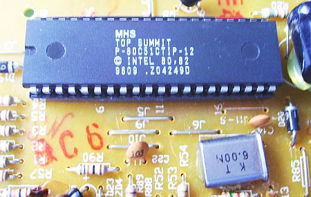
At the heart of the machine is the processor chip manufactured by Intel. Also clearly visible is the quartz crystal (KT 6.00) used to control the processor clock and all the timing functions of the bread maker. This is a 6 MHz clock.
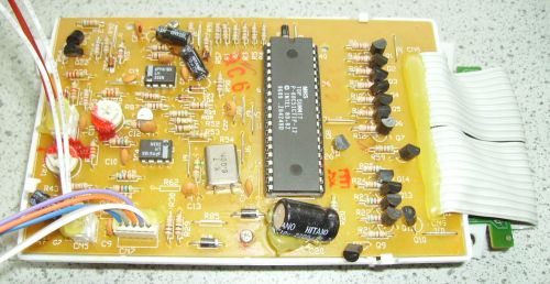
This shows the whole processor circuit board. The transistors are used to drive the LEDs and the seven segment displays. They are needed because the processor itself can not provide sufficient current to drive these output devices.
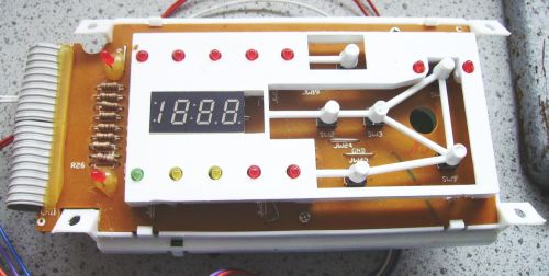
Here is the user interface of the machine. The seven segment display normally shows the time till the bread is ready but it also shows other numerical information while the cook is programming the machine. There are LED indicators to show what the machine is doing. There are six push-button switches mounted via bendy plastic strips. These are used to program the machine by selecting preferences like pale/medium/dark crust. There is also an option simply to knead the dough without cooking.
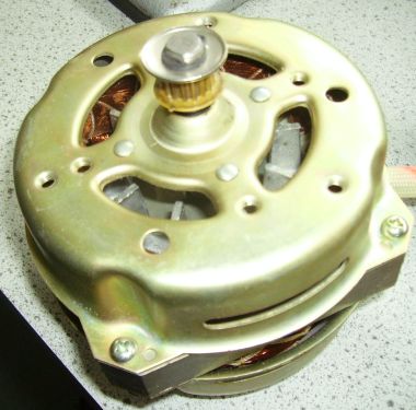
The motor is used to knead the dough. This is a fairly high powered motor because dough is heavy and stiff.
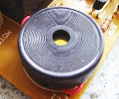
The bread maker produces warning beeps. For example, near the end of the dough kneading, there is an option to add seeds for more exotic loaves. When it is time to add the seeds, the sounder beeps.
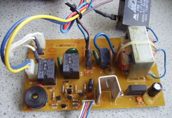
This is the 230 volt circuit board. You can see a transformer used to produce the low voltage needed by the processor board. Also the power supply rectifier diodes are visible. There are two relays used to power the motor forwards and in reverse. There is a big black capacitor at the top of the image. This is also part of the motor direction control. It is a little unusual because of its high voltage rating (450V) and its ability to work in AC circuits.
Contact, Copyright, Cookies and Legalities: C Neil Bauers - reviseOmatic V4 - © 2016 to 2026
Hosted at Akamai Cloud - London
Please report website problems to Neil