WANTED: Individual or team to take over this project. I'm in my 70's and want to put my feet up. Contact details in footer.
PIC16F88 0F LED Matrix |
|
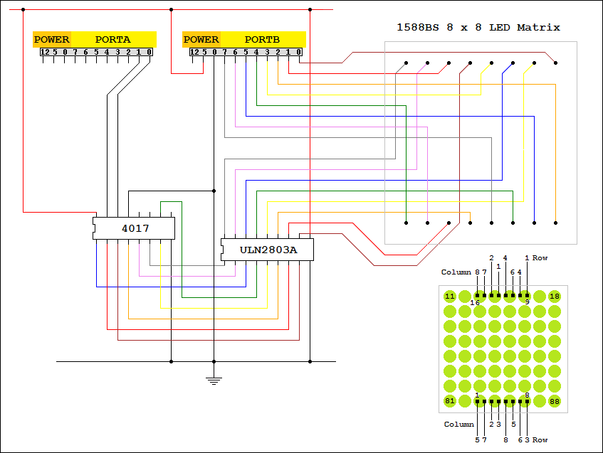
The microcontroller can drive the rows with 9 or 10 mA per LED or port pin.
The columns might have as many as eight lit LEDs with up to 80 mA per colum. This exceeds the microcontroller pin current limit by a large margin.
The ULN2803A solves the problem by acting as the column driver.
There are not enough output pins on PORTA to drive the eight columns. A solution to this problem could be to use a microcontroller with more I/O pins.
Another solution us to use the 4017 decade counter as a shift register.
RA0 clocks this chip to move the single active output one place to the right.
RA1 is used to reset the counter at the correct moment. If it went out of sync for any reason, it would be corrected in a few milliseconds.
Each column is lit for 1/8th of the time. This makes the LEDs less bright. The LED current could be increased a little with this circuit without overloading the MCU.
A better solution would be to use a purpose designed driver chip. The MIC5891 chip is ideal but is beyond the scope of this tutorial.
Uning the MIC5891 chip, it becomes possible to control multiple displays.
Contact, Copyright, Cookies and Legalities: C Neil Bauers - reviseOmatic V4 - © 2016 to 2026
Hosted at Akamai Cloud - London
Please report website problems to Neil