
RANDOM PAGE
SITE SEARCH
LOG
IN
SIGN UP
HELP
To gain access to revision questions, please sign up and log in.
A2
aA Generic Diagram
Here is a diagram representing a generalised control system.
Open loop control systems do not have any feedback or an error detector so the diagram can be simplified.
bInput Instructions
Control systems have input sensors which generate signals that instruct the system to act. The instructions specify what the control system should do. It could be something simple like a voltage used to specify how bright a lamp should be. It could be more complex like a binary code used to change a TV channel. Here are some examples ...
- Resistive Transducers:
- Switches:
- Start, Stop, Reset, Sense machinery position.
- Combination Lock.
- Pressure mat.
- Resistors
- LDR for light level measurement.
- Thermistor for temperature measurement.
- Potentiometer for angle measurement.
- Potentiometer for setting a reference voltage.
- Strain gauge.
- Sound sensors:
- Microphone, Ultrasound sensor.
- Time information:
- Astable produces timed pulses which trigger the control system to act.
- A microcontroller that has computer code to instruct the control system to act.
cProcess
- Digital logic circuit
- Logic gates, Counters, Shift registers, Latches.
- Microcontroller
- Analogue input.
- Digital inputs and outputs.
- Analogue circuits
- Comparator.
- Schmitt trigger.
- Summing Amplifier.
- Difference Amplifier.
|
dDrivers
These are needed to drive the output transducers. Mostly the processor has insufficient power to drive these output devices. If higher power circuits like railway locomotives need to be controlled, complex high power driver circuits are needed. Most output devices need some sort of driver.
- MOSFET Switch
- MOSFET Source Follower
- BJT Switch
- BJT Emitter Follower
- Voltage Follower
- Relay
- H Bridge Driver
eOutput
It could be anything from a single light bulb to the avionic controls for an entire aircraft.
- Motors
- Conventional
- Stepper
- Servo
- Light
- Bulbs
- LEDs
- LASERs
- LED Displays
- LCD Displays
- Sound
- Piezoelectric Sounder
- Loud Speaker
- Buzzer
- Siren
|
- A: Input Instructions
- B: Error Detector (Often subtracts the error from the input)
- C: The Processor
- D: Transducer Driver
- E: Output Transducer / Device
- F: Feedback Sensor (Measures the output)
- P: Human interface device signal. For example a rotary switch for cruise control with settings for 30, 40 ... 70 mph.
- Q: Instructions to the processor. For example the switch above could generate voltage that depends on the wanted speed. 3V = 30 mph, 7V = 70 mph.
- R: The input signal with the negative feedback subtracted. If the control system has settled on its final steady state, this signal would usually be zero. Any deviation from the settled state creates a signal used to correct the error. -1 Volts would mean 10 mph too fast.
- S: The processor takes the input DC voltage and turns it into a control signal suitable for the driver for the output transducer. This might be the width of a stream of pulses used to control the position of a servo.
- T: A higher powered signal able to drive the output transducer.
- U: The final output of the control system
- V: A signal into the feedback sensor. For example a stream of pulses from a slotted disc.
- W: A signal from the feedback sensor. For example the slotted disc pulse stream can be turned into a DC level where 3V = 30 mph and 7V = 70 mph.
fClosed Loop Control System
gNegative Feedback
Closed loop control systems always include negative feedback. This is where the output is measured in order to control the output.
- Measure speed in order to control the speed. (Cruise Control).
- Measure the temperature to control the temperature. (Heating thermostat).
- Measure the room light level to control the the room lighting.
Beware of trick feedback scenarios where the thing being measured is not the output.
- Measure the room light level to control the display screen brightness. (This is not feedback).
- Adjust a potentiometer to set the the room light level. (This is not feedback).
hVehicle Cruise Control Example
- The input instruction could be a 6 Volt signal used to represent 60 miles per hour.
- The output sensor measures the actual output (vehicle speed - 5 volts might represent 50 miles/hour).
- The error detector measures the difference between the required and actual output (-1 volts represents 10 miles/hour too slow)
- The processor interprets the signal from the error detector and generates an output signal.
- This could be a very crude process giving either maximum throttle or none - uncomfortable.
- The processing could be much smoother, increasing the throttle until the vehicle is accelerating at a comfortable rate.
- The output transducer driver converts the processor output to the correct format to control the output device. In this case the transducer driver uses the small signal from the processor to control the throttle setting.
- The feedback loop is the path from the output back to the input. In all closed loop systems, this is negative feedback. It is used to correct errors in the output.
- Positive feedback causes the output to swing rapidly to one extreme or the other while negative feedback tends to correct the output so it reaches an appropriate middling value.
iOpen Loop Control Systems
- These are simpler because there is no feedback.
- In all the cases below, the output is not measured.
- Input signals instruct the processor and the output performs a useful task such as ...
- Room light dimmer
- Metronome for a musician
- Activate marine buoy signal lights when it gets dark
- Turn on street lights when it gets dark
- A: Instructions
- B: Processor
- C: Driver
- D: Output Device
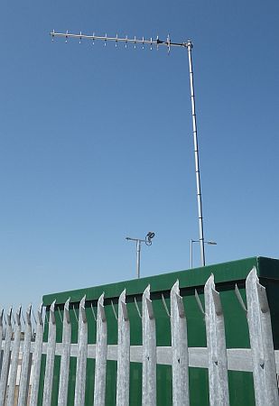
jSewage Pumping Remote Control Vertically Polarised Yagi Antenna
Here is a pumping station, linked by radio to a central control station. If the pumps failed, sewage could flow in the streets so keeping track of the state of the pumps is important for public health, never mind the complaints if it all went wrong.
Broadcast TV is mostly horizontally polarised so this antenna is mounted vertically to minimise the chances of interference between the TV and Water Company services.
reviseOmatic V3
Contacts, ©, Cookies, Data Protection and Disclaimers
Hosted at linode.com, London