
Position Sensing |
|
To gain access to revision questions, please sign up and log in.
a
These are devices used to count the revolutions of rotating shafts.
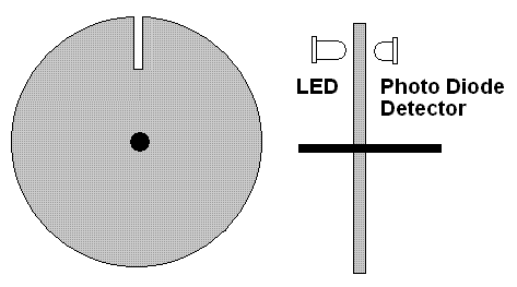
Here is a simple arrangement that gives one pulse for each shaft rotation. It can be used to measure vehicle speed or engine RPM (revolutions per minute). Infrared light is generally used because there is too much visible light in the environment for reliable operation.

Here is another arrangement used in computer mice of the ball variety.

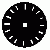
The wheel above has 16 slots.

A wheel painted with black and white zones can be used too. This relies on the measurement of reflected light.
All the devices, above, measure rotation but not absolute position.
d
eGray Code Scale Absolute Position (Better)Four photo detectors measure the colour of the four stripes on the wheel. This pattern is a binary code that is designed such that only one stripe changes colour at any given position. This means that the Gray code does not suffer from incorrect wheel position problems. With four tracks (stripes) 16 positions can be detected. This is a 2N calculation so 24 = 16. With 8 tracks 28 positions can be measured = 256.
Gray code can be used for straight line movement measurement too.
|
fBinary Coded Scale Absolute Position (Problems)Four photo detectors sense the position of the wheel from the binary output. This arrangement has one serious disadvantage. As the wheel rotates, at certain positions, more than one bit changes state. If the sensors are slightly misaligned, this can lead to large errors in the apparent wheel position. The numbers in the diagran show how many bits change at each transition.
Linear movement can be sensed with a binary coded scale but this suffers from the same limitation as the circular scale above.
|
This is a device that produces a voltage proportional to the speed of a rotating shaft. Common examples include the rev' counter found in many vehicles. This measures the rotation of the engine crank shaft. The speedometer in vehicles measures the wheel rotation speed. Wind speed gauges use a similar system.
Here is a convenient way to detect the rotation of a shaft.

Shaft rotation can also be measured with a mirror attached to the shaft. Another alternative is to attach a magnet to the shaft and place an induction coil near the magnet. As the magnet passes the coil, a voltage pulse will be induced.
As the notched wheel rotates, the light beam is interrupted. This appears as a small square(ish) wave output from the photodiode. When the shaft rotates faster, more pulses are produced but the pulses are also shorter. This means that the average output remains constant. To make a useful measuring device, the variable length pulses from the photodiode need to be converted into fixed length pulses. A monostable circuit achieves this. The monostable needs to be triggered by short pulses.
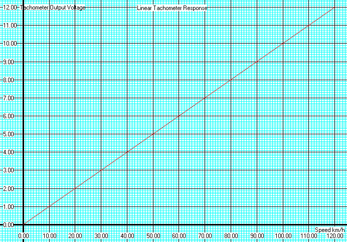
hThis is a linear system. This means that the tachometer output voltage is directly proportional to the speed. A graph plot gives a straight line as shown below. This system has been neatly calibrated to give one volt representing ten km/h.
A Graph of Tachometer Voltage Output against Speed

reviseOmatic V3 Contacts, ©, Cookies, Data Protection and Disclaimers Hosted at linode.com, London