View Index by Level
RANDOM PAGE

SITE SEARCH

LOG
IN

SIGN UP

HELP

Interfacing


This is the AQA version closing after June 2019. Visit the the version for Eduqas instead.

To gain access to revision questions, please sign up and log in.

Everyone

Techniques

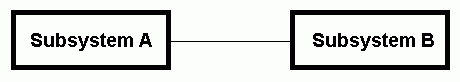
Interfacing transfers a signal from one subsystem to another.

Interfacing techniques include ...

Simple wire connections.

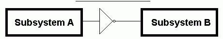
This applies to most logic gates which are designed to be directly connected.

Interfacing-Wire.gif

Coupling capacitors.

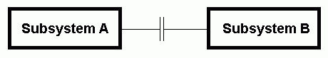
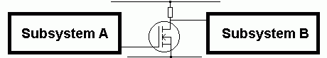
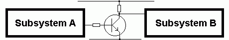
These pass A.C. signals (audio or radio) from one subsystem to the next while blocking D.C. potentials.

Interfacing-Capacitor.gif

Follower circuits.

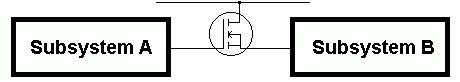
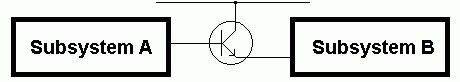
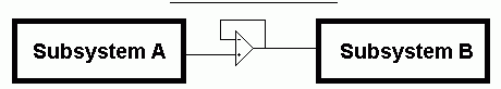
These boost the available current or power and have minimal effect on the voltage.

MOSFET Source Follower

Interfacing-Source-Follower.gif

BJT Emitter Follower

Interfacing-Emitter-Follower.gif

Operational Amplifier Voltage Follower

Interfacing-Voltage-Follower.gif

Pulse Inverters

NOT Gate

Interfacing-Not-Gate.gif

MOSFET Switch

Interfacing-MOSFET-Switch.gif

BJT Switch

Interfacing with a Bipolar Transistor Switch

Pulse shortener or Differentiator

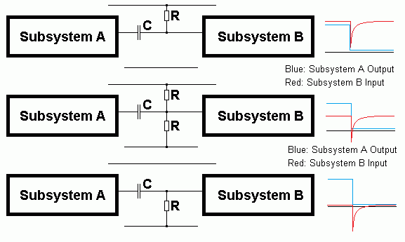
This is an RC timing circuit which copies the input pulse to the output but then quickly reverts back to its original state; high, middling or low in the three diagrams below.

The middle version of this circuit is useful if you need an op-amp to trigger a 555 monostable.

Interfacing-RC-Differentiators.gif

Pulse smoothing or Integrator

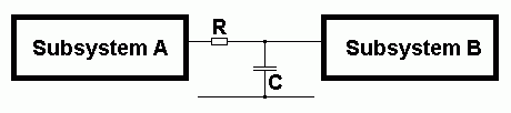
This is an RC timing circuit which smooths a rapidly varying voltage to its average.

Interfacing-RC-Integrator.gif

Peak Level Detection

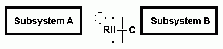
This provides a DC Voltage equal to the peak AC input. This DC level dies away slowly depending on the values of R and C.

Interfacing-RC-Diode-Peak-Level.gif

Volume Control

A potentiometer is used as a voltage divider. The slider can be moved from 0% to 100% of the signal voltage. One or two coupling capacitors might also be needed.

Interfacing-Volume-Control.gif

Trigger Pulses

Differentiator to Shorten Pulsesa

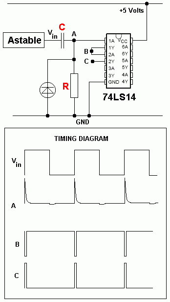
This circuit converts the square waves from a source like an astable into very short fixed length trigger pulses.


  • The sharp edges of the square wave pulses (Vin) are passed through the capacitor C.
  • The resistor R quickly discharges the capacitor. Look at "A" on the diagram below.
  • The inverting Schmitt Trigger converts the oddly shaped pulses into neat square pulses. Look at "B" on the diagram below.
  • The negative pulses are prevented with the diode.
  • The second Schmitt Trigger inverts the pulses.
  • Look at "C" on the diagram below.
  • This stage is only needed if short positive pulses are wanted.
  • The length of the short pulses in "B" and "C" below depends on the values of R and C.
  • The approximate pulse length T can be roughly estimated using T = RC.


reviseOmatic V3     Contacts, ©, Cookies, Data Protection and Disclaimers Hosted at linode.com, London