Home
Home
rOm
Quest
Glossary
Random
Page
Search
Site
Lush
Sim
Class
Subject
Images
Help
FAQ
Sign
Up
Log
In
WANTED: Individual or team to take over this project. I'm in my 70's and want to put my feet up. Contact details in footer.
Uses
-
drive loudspeakers
-
amplify radio frequency energy before feeding to the antenna
-
drive DC motors. Both speed and direction can be controlled. (An H-Bridge controller would usually be preferred.)
Source Followers
-
The N Channel MOSFET provides power amplification for the positive part of the AC input.
-
The P Channel MOSFET provides power amplification for the negative part of the AC input.
-
The voltage gain is 1
-
No output coupling capacitor is needed (avoiding the use of a physically big component). Single ended (not push pull) amplifiers need a big output coupling capacitor.
-
When there is no input, neither MOSFET is conducting. This saves energy. Single ended amplifiers consume power even when there is no input.
-
When there is an AC input, each MOSFET is conducting for only 50% of the time.
Power Output (Ideal Circuit)
PMAX = VRMS2 / RL = VS / (2 RL) There is more information on the Power and RMS page.
-
PMAX is the maximum power output.
-
VRMS is the maximum RMS amplifier output voltage.
-
VS is the power supply voltage and also the peak amplifier output voltage.
-
RL is the load resistance, often 4 or 8 ohms for loudspeakers.
Cross Over Distortion
This simple circuit suffers from cross over distortion.
The red trace is the input signal. The blue trace is the output.
-
Quite a large input voltage is needed to turn on the FETs, 2 to 4 Volts.
-
This has an unwanted side effect. The output is 2 to 4 volts less than the ideal case.
-
A positive potential will turn on the top N Channel FET.
-
A negative potential will turn on the bottom P Channel FET.
-
Small potentials close to zero will turn on neither FET.
-
This causes severe cross over distortion, most noticeable with quiet music.
-
The amplifier works fairly well for potentials greater than +/- 2 to 4 volts but hardly works at all for lower potentials.
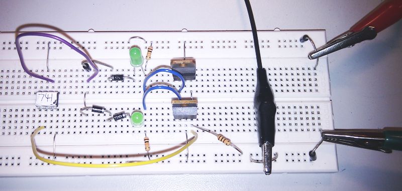
Bias the MOSFETs
This diagram shows simple biasing using diodes and resistors. 0.7 Volts is lost across the diodes so the output will be lower than expected compared with using ideal components. It is possible to use LEDs. In this case about two Volts will be lost.
Use Negative Feedback
-
This circuit uses both biasing and negative feedback to improve performance.
-
The LEDs have two volts across them. This helps to reduce cross over distortion. This is an unusual way of biasing the MOSFETs but it works.
-
The MOSFETS are included in the feedback path.
-
The Op Amp voltage follower uses a higher power supply voltage. This allows the MOSFET source follower outputs to swing over a larger range of voltages.
The red trace is the input signal. The blue trace is the output. The distortion has gone.
This push-pull amplifier uses a voltage follower and MOSFET biasing. It runs on + and - 12 Volts and is similar to the diagram above.
-
This circuit has a voltage gain of 1 but a much higher power gain (power_out / power_in).
-
The Op amp output potential will be just right to ensure that Vout = Vin
-
Negative feedback is being used to correct for errors in the output.
-
The operational amplifier is wired up as a voltage follower so Vout should track Vin exactly.
-
Cross over distortion is minimised.
Push Pull Advantages
-
Don't need a large coupling capacitor between the output and the speaker.
-
Very low power consumption when the input signal is absent or small.
-
In other types of amplifier, this capacitor limits the low frequency response (high pass filter).
Push Pull Disadvantages
-
Cross Over Distortion
-
MOSFETs have good high frequency properties. Usually this is an advantage but it makes it easy to build an accidental oscillator capable of high power outputs. The oscillations are likely to be outside the range of human hearing but still able to overheat and destroy speakers, usually the tweeters. Careful design is needed.
Saturation, Clipping, Limiting
-
An ideal op amp could provide an infinite output voltage range.
-
A very good op amp could provide outputs at least up to the power supply voltages.
-
Most op amps fall short by about two volts so with a 12 volt supply, the output would be only ten volts.
-
The output should be directly proportional to the input. That is perfectly linear.
The image below shows ideal (black) and non-ideal (red and blue) behaviour including clipping when the op amp is saturated and the output voltage can go no higher.
Amplifiers of any type can not produce output voltages that are larger than the power supply voltages. If the input is too big, the amplifier output will increase until it is nearly equal to the supply voltage. After that the output voltage can not rise any more. The black line shows the amplifier input signal. The red line shows the output from the N Channel MOSFET. The blue line shows the output from the P Channel MOSFET.
Circuit suffering from Clipping, Saturation or Limiting
This can be eliminated by using a higher power supply voltage as long as all the components can handle this and also the extra waste heat produced.
Bipolar Transistor Push Pull
Before the invention of the MOSFET, versions of this circuit were very commonly used.
To prevent cross over distortion, the emitter followers are biased using a combination of resistors and diodes.
This circuit uses negative feedback to further reduce distortion.
All the MOSFET material above also applies to this circuit.
Since MOSFETs are superior in almost all respects, this circuit is now rarely found.
MOSFETS ...
-
are more linear so there's less distortion.
-
have a higher frequency response.
-
conduct less well as they heat up so thermal runaway is less likely.
-
have a lower resistance so less energy is wasted as heat.
-
are voltage driven so less current is needed from the pre-amplifier/s
MOSFETs lose more voltage (gate source 2 to 4 volts) than bipolar transistors (base emitter 0.7 volts).
This disadvantage can be overcome by using a slightly higher power supply voltage.
Subject Name
Level
Topic Name
Question Heading
First Name
Last Name Class ID
User ID
Question Text
image url
Help Link
Add
Delete
Clone
Edit
Hardness
Help Text
Debug
- You can attempt a question as many times as you like.
- If you are logged in, your first attempt, each day, is logged.
- To improve your scores, come back on future days, log in and re-do the questions that caused you problems.
- If you are logged in, your most recent wrong answers get remembered. This might help you and your teacher to correct your understanding.
- In the grade book, you can delete your answers for a topic before re-doing the questions. Avoid deleting unless you intend re-doing the questions very soon.