 Home
Home
rOm
Quest
Glossary
Random
Page
Search
Site
Lush
Sim
Class
Subject
Images
Help
FAQ
Sign
Up
Log
In
WANTED: Individual or team to take over this project. I'm in my 70's and want to put my feet up. Contact details in footer.
Simple Radio - System Diagram / Circuit Diagram
This topic is unlikely to be in an exam but it might be useful for project work.
-
The receiving antenna (A) converts radio waves (electromagnetic radiation) into a radio frequency alternating voltage or current.
-
At position (B) there are many radio signals because filtering has not yet taken place.
-
The tuned circuit (C and D) selects the wanted frequency (radio station) and rejects other frequencies.
-
At position (E), there should be only one radio frequency signal because the tuned circuit has SELECTED the wanted frequency and rejected others.
-
At position (F) after the diode demodulator, the information signal (music, speech, remote control data) has been separated from the from the modulated radio frequency signal.
-
The decoupling capacitor at position (G) removes the radio frequencies by passing them to ground. The audio information signal remains and goes to the headphones.
-
The output transducer ((H) headphones in the diagram above) converts the information signal into it's final form (often music and voice).
Terminology
-
Sensitivity: The ability to receive weak signals. A good antenna helps. A radio frequency amplifier helps too.
-
Selectivity: The ability to tune in one frequency or station and reject others on close frequencies. The tuned circuit does this.
-
Modulation: The radio frequency carrier signal is modified by the information signal.
-
Demodulation: The information signal is separated from the modulated carrier. The diode does this.
-
AM: Amplitude modulation. The amplitude (size) of the radio frequency carrier signal is modified in step with the information signal.
-
FM: Frequency modulation. The frequency of the radio frequency carrier signal is modified in step with the information signal.
-
RF: Radio frequency.
-
AF: Audio frequency.
Advantages
-
It is simple to construct.
-
It's cheap.
Disadvantages
-
Poor Sensitivity. This can be overcome with RF and AF amplification.
-
Very poor Selectivity because there is only one tuned circuit for filtering.
-
It is very difficult to add additional tuning stages.
-
This is because it is hard to manufacture exactly matched variable capacitors. They are very expensive.
-
This problem gets worse at higher frequencies.
Carrier Wave, Information Signal and Modulation
-
A microphone converts sound waves (energy) into an electrical signal (energy) proportional to the sound wave pressure.
-
This is called the Information Signal.
-
These frequencies are too low to transmit.
-
A high frequency radio frequency Carrier Wave is needed.
-
This can be transmitted.
-
In the Transmitter, the carrier wave is Modulated (varied) by the signal from the microphone.
-
In the Receiver the signal is Demodulated to get back the original information signal.
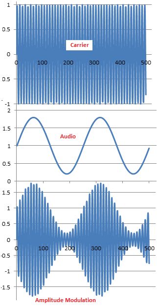
Amplitude Modulation
AM transmitters vary the amplitude of the carrier wave.
-
The amplitude of the carrier wave is proportional to the amplitude of the signal being modulated.
-
If the modulation signal frequency increases, the amplitude of the carrier changes at a greater rate.
-
A radio frequency carrier is needed.
-
As the audio waveform rises and falls, the carrier amplitude increases and decreases in direct proportion.
-
As the audio amplitude increases, the modulation of the carrier increases.
-
If the audio frequency rises, the carrier amplitude varies faster, in step with the audio signal.
-
The carrier frequency does not change.
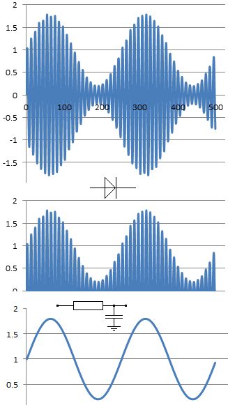
AM Demodulation or Detection
-
A diode is used to pass the radio frequency signal in one direction only.
-
A low pass RC filter is used to pass the audio frequencies and decouple or smooth out the radio frequencies.
-
Silicon diodes are not ideal because 0.7 volts is needed before the diode starts to conduct.
-
Germanium diodes are better because only 0.2 volts is needed.
-
Active circuits are even better because these can mimic an ideal diode.
Frequency Modulation
FM transmitters vary the frequency of the carrier wave.
-
The frequency change of the carrier wave is proportional to the amplitude of the signal being modulated.
-
If the modulation signal frequency increases, the frequency change of the carrier changes at a greater rate.
-
The amplitude of the carrier does not change.
FM on a Picoscope
-
The blue is the carrier.
-
The red is the sound wave being modulated.
-
Real life FM does not change the frequency so much and it would be hard to see on a trace like this.
Advantages of FM
The sound quality is better with a wider range of frequencies being faithfully reproduced.
FM is transmitted on the VHF band. There is less radio interference on this band so the signals are clearer.
FM is much less affected by amplitude noise from lightning strikes or industrial machinery so the sound is clearer.
At night AM radio signals from distant transmitters interfere with the local transmitters so AM radio is not so good.
FM Disadvantages
The transmitters have a range of only 20 to 50 miles depending on the terrain so more transmitters are needed to cover the country.
AM transmitters on the Medium Frequency or Medium Wave band have a range up to several hundred miles. Fewer transmitters are needed to cover the country.
FM radios cost more to build because they are more complex than AM.
Subject Name
Level
Topic Name
Question Heading
First Name
Last Name Class ID
User ID
Question Text
image url
Help Link
Add
Delete
Clone
Edit
Hardness
Help Text
Debug
- You can attempt a question as many times as you like.
- If you are logged in, your first attempt, each day, is logged.
- To improve your scores, come back on future days, log in and re-do the questions that caused you problems.
- If you are logged in, your most recent wrong answers get remembered. This might help you and your teacher to correct your understanding.
- In the grade book, you can delete your answers for a topic before re-doing the questions. Avoid deleting unless you intend re-doing the questions very soon.