WANTED: Individual or team to take over this project. I'm in my 70's and want to put my feet up. Contact details in footer.
| AS Level Semiconductor Diode >Rectifier and PSU< Zener Diode |
Semiconductor Rectifier and PSU |
|
Rectifier diodes convert AC into DC by passing current in one direction only.
In the image below ...
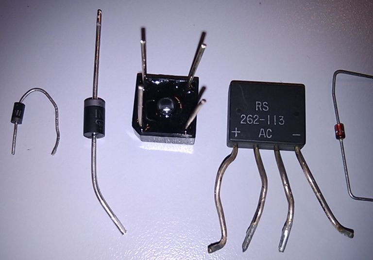
Most electronic circuits need low voltage direct current (DC).
To minimise energy loss in power lines, the power companies use high voltage alternating current (AC) for power distribution. This is because it's possible to step the voltage up or down using transformers. High voltage transmission is more efficient. Power supply circuits step the mains voltage down to a suitable value and produce direct current.
Here are some examples. The transformer steps the voltage down to a suitable low value. The diode/s only pass current in one direction so the AC is converted to DC. The capacitor stores charge and smooths out the raw DC. To get really good smoothing, electronic regulation is needed in addition to the capacitor used to store charge.
These sketches show ...
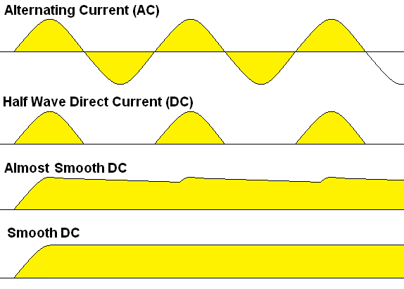
The half wave rectifier is the simplest and least satisfactory. It is called a half wave rectifier because the diode only conducts for half the time. 0.7 Volts is lost across the diode. Here are some improved circuits.
This is a full wave rectifier using a transformer with a centre connection to the secondary coil. 0.7 Volts is lost across each diode.
This is a bridge rectifier. This is the best solution. It has a simple transformer and full wave rectification. 1.4 Volts is lost across the diodes.
These sketches show ...
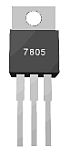
Here is a voltage regulator circuit using the 7805 chip. This produces very smooth DC at exactly 5 Volts. Other voltages are possible too.
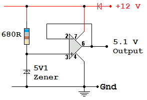
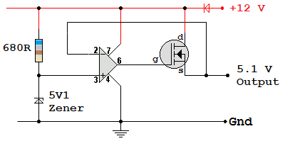
Using a high power version of an op-amp, this circuit could (left) provides a stable 5.1 Volt output up to 10 Amps or whatever the op-amp rating is.
The resistor and Zener diode combination, on its own, can only stabilise a few milliamps of load current.
The right hand circuit uses a standard op-amp with a MOSFET source follower or a bipolar transistor emitter follower.
Power supplies should produce a constant output voltage over a range of line input voltages. For example many lap-top power supplies and phone chargers will work correctly for any line voltage between 100 and 250 Volts. This means they can be used in most countries of the world without any worries.
Power supplies should maintain a constant output voltage, even if the output load current varies. Load regulation is a measure of how well a power supply manages to achieve this.
This formula calculates the percentage output change between minimum and maximum loads where Vmid is the nominal rated output.
%Regulation = 100 x ( ( Vmin - Vmax ) / Vmid )
Subject Name Level Topic Name Question Heading First Name Last Name Class ID User ID
|
Q: qNum of last_q Q ID: Question ID Score: num correct/num attempts Date Done
|
Question Text
image url
Help Link
Add Delete Clone Edit Hardness
Contact, Copyright, Cookies and Legalities: C Neil Bauers - reviseOmatic V4 - © 2016 to 2026
Hosted at Akamai Cloud - London
Please report website problems to Neil