Site Logo Home
 
rOm
Quest
Glossary
 
Random
Page
Search
Site
Lush
Sim
Class
Subject
Images
 
Help
FAQ
Sign
Up
Log
In
A Level     >AC Circuits<     Active Filters     Passive Filters     Tuned Circuits    

AC Circuits


Site for Eduqas/WJEC - Go to the AQA site.

  A Level    Filters  0 of 38    Question 301    A2 Sub-systems 
Score 0/0 
Not attempted  
Last Answer  
Deadline not set1 of 38    Question 639    Active LPF 
Score 0/0 
Not attempted  
Last Answer  
Deadline not set2 of 38    Question 638    Active LPF 
Score 0/0 
Not attempted  
Last Answer  
Deadline not set3 of 38    Question 640    Active LPF 
Score 0/0 
Not attempted  
Last Answer  
Deadline not set4 of 38    Question 641    Active LPF 
Score 0/0 
Not attempted  
Last Answer  
Deadline not set5 of 38    Question 642    Active LPF 
Score 0/0 
Not attempted  
Last Answer  
Deadline not set6 of 38    Question 643    Active LPF 
Score 0/0 
Not attempted  
Last Answer  
Deadline not set7 of 38    Question 644    Active LPF 
Score 0/0 
Not attempted  
Last Answer  
Deadline not set8 of 38    Question 595    Capacitative Reactance 
Score 0/0 
Not attempted  
Last Answer  
Deadline not set9 of 38    Question 1219    Capacitor Uses 
Score 0/0 
Not attempted  
Last Answer  
Deadline not set10 of 38    Question 344    Op Amp Circuits 
Score 0/0 
Not attempted  
Last Answer  
Deadline not set11 of 38    Question 347    Op Amp Circuits Filters 
Score 0/0 
Not attempted  
Last Answer  
Deadline not set12 of 38    Question 346    Op Amp Circuits Filters 
Score 0/0 
Not attempted  
Last Answer  
Deadline not set13 of 38    Question 345    Op Amp Circuits Filters 
Score 0/0 
Not attempted  
Last Answer  
Deadline not set14 of 38    Question 522    Passive Filters 
Score 0/0 
Not attempted  
Last Answer  
Deadline not set15 of 38    Question 28    RC Filter Break Point - Calculation 
Score 0/0 
Not attempted  
Last Answer  
Deadline not set16 of 38    Question 27    RC Filters - Basics 
Score 0/0 
Not attempted  
Last Answer  
Deadline not set17 of 38    Question 7    RC Filters - Basics 
Score 0/0 
Not attempted  
Last Answer  
Deadline not set18 of 38    Question 295    Sub-systems 
Score 0/0 
Not attempted  
Last Answer  
Deadline not set19 of 38    Question 292    Sub-systems 
Score 0/0 
Not attempted  
Last Answer  
Deadline not set20 of 38    Question 293    Sub-systems 
Score 0/0 
Not attempted  
Last Answer  
Deadline not set21 of 38    Question 1412    Tuned Circuit Calculation 
Score 0/0 
Not attempted  
Last Answer  
Deadline not set22 of 38    Question 91    Tuned Circuit Calculation 
Score 0/0 
Not attempted  
Last Answer  
Deadline not set23 of 38    Question 360    Tuned Circuit Calculation 
Score 0/0 
Not attempted  
Last Answer  
Deadline not set24 of 38    Question 1361    Tuned Circuit in Radio 
Score 0/0 
Not attempted  
Last Answer  
Deadline not set25 of 38    Question 100    Tuned Circuit Properties 
Score 0/0 
Not attempted  
Last Answer  
Deadline not set26 of 38    Question 99    Tuned Circuit Properties 
Score 0/0 
Not attempted  
Last Answer  
Deadline not set27 of 38    Question 98    Tuned Circuit Properties 
Score 0/0 
Not attempted  
Last Answer  
Deadline not set28 of 38    Question 97    Tuned Circuit Properties 
Score 0/0 
Not attempted  
Last Answer  
Deadline not set29 of 38    Question 96    Tuned Circuit Properties 
Score 0/0 
Not attempted  
Last Answer  
Deadline not set30 of 38    Question 74    Tuned Circuit Properties 
Score 0/0 
Not attempted  
Last Answer  
Deadline not set31 of 38    Question 73    Tuned Circuit Properties 
Score 0/0 
Not attempted  
Last Answer  
Deadline not set32 of 38    Question 102    Tuned Circuit Properties 
Score 0/0 
Not attempted  
Last Answer  
Deadline not set33 of 38    Question 101    Tuned Circuit Q Calculation 
Score 0/0 
Not attempted  
Last Answer  
Deadline not set34 of 38    Question 94    Tuned Circuit Q Factor 
Score 0/0 
Not attempted  
Last Answer  
Deadline not set35 of 38    Question 104    Tuned Circuit Q Factor 
Score 0/0 
Not attempted  
Last Answer  
Deadline not set36 of 38    Question 599    Tuned Circuits 
Score 0/0 
Not attempted  
Last Answer  
Deadline not set37 of 38    Question 92    Tuned Circuits and Phase 
Score 0/0 
Not attempted  
Last Answer  
Deadline not set38 of 38    Question 901    Tuned Circuits and Phase 
Score 0/0 
Not attempted  
Last Answer  
Deadline not set  Questions 0 to 38   -->  View All  

RC Circuits

At high prequencies, capacitors pass currents as easliy as wire.

DC and low frequencies are blocked by capacitors.

This blocking effect is called REACTANCE ( XC ) and it's similar to resistance but it depends on frequency.

XC = 1 / ( 2 π f C )

RC Filter Loading

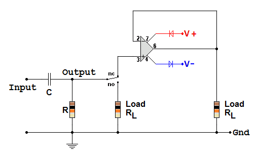
The circuit above shows an RC high pass filter connected to a choice of two loads. SIMULATION

  1. RL is a 10 K resistor.
    When the output is switched to this load, the two 10 K resistors are placed in parallel.
    This completely changes the performance of the filter.
    The circuit could be designed to take this into account or option 2 below could be used instead.
     
  2. With the switch in the top position, the op-amp voltage follower has a very high input impedance.
    In this case, the filter performance is not altered by connecting the load.
    Often this is the preferred option.
    Other non-inverting amplifiers also have a very high input impedance and are aslo suitable.
    This use of a voltage follower is called BUFFERING. The filter is ISOLATED from the next sub-system in the circuit.

RL Circuits

Inductors pass DC and low frequencies just like wire although they often have more resistance than a short wire.

At high frequencies, inductors block AC signals.

This blocking effect is called REACTANCE ( XL ) and it's similar to resistance but it depends on frequency.

Inductors have a couple of disadvantages. They can be bulky and waste heat can be generated due to the DC resistance of the wire making them less efficient.

XL = 2 π f L


Comparing L and C Current Lag and Lead

Capacitor - The current leads the voltage. To charge or fill a capacitor, a current has to flow. As it fills, the voltage across the capacitor builds up, like the water level in a bucket. Once it's nearly full, this voltage reaches its maximum and the current dies away to zero. Note that this is the voltage across the capacitor and not the external voltage causing it to charge in the first place.

Inductor - The current lags the voltage. Inductors only have a voltage across them if the current is changing. With a steady current, the voltage across an ideal inductor would be zero because its resistance is zero. Whenever the current changes, the altering magnetic field induces a back EMF that opposes the change in current.

Phase - This is the angle 90o or, in radians, π / 2 between the voltage and the current. This is a quarter of a cycle of the wave.

Subject Name     Level     Topic Name     Question Heading     First Name Last Name Class ID     User ID    

fff
Home
<<<
ppw
Pg Up
<<
ppp
Up
<
|||

>|<
nnn
Down
>
nnw
Pg Down
>>
lll
End
>>>

Close
Escape
X

Q: qNum of last_q     Q ID: Question ID         Score: num correct/num attempts         Date Done    


Submit
Enter


Question Text

image url


Help Link

Add     Delete     Clone     Edit     Hardness

Help Text
Debug


Contact, Copyright, Cookies and Legalities: C Neil Bauers - reviseOmatic V4 - © 2016/17

Hosted at linode.com - London


Please report website problems to Neil