 Home
Home
rOm
Quest
Glossary
Random
Page
Search
Site
Lush
Sim
Class
Subject
Images
Help
FAQ
Sign
Up
Log
In
WANTED: Individual or team to take over this project. I'm in my 70's and want to put my feet up. Contact details in footer.
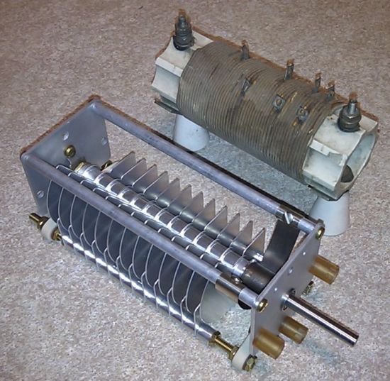
An inductor and variable capacitor designed for high transmitter voltages.
Tuned Circuit Properties
-
Tuned circuits consist of an inductor coil and a capacitor (often variable).
-
A tuned circuit has a very high impedance at its resonant frequency (ideally = infinity).
-
At other frequencies, its impedance is lower.
-
Tuned circuits are used to select or tune in radio stations on a particular frequency and reject all the others.
At the resonant frequency ...
-
the voltage across the tuned circuit is at its maximum value
-
the capacitor and inductor have equal effect on the circuit because they have equal reactance. XL = XC
-
the current in the capacitor is equal to the current in the inductor
-
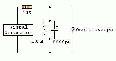
the current in the tuned circuit is in phase with the signal generator voltage (see diagram below)
-
the current (to ground/earth) through an ideal tuned circuit will be zero
Tuned Circuit Measurements
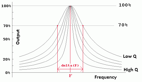
Q or Quality Factor
-
High Q tuned circuits respond to a narrow range of frequencies giving a sharp narrow peak in the graph above.
-
Low Q tuned circuits respond to a wider range of frequencies giving a lower and broader peak in the graph above.
-
A receiver with a higher Q tuned circuit will be more selective. It will be better at receiving the wanted signal and rejecting signals on adjacent channels.
-
Q = f0 / delta(F).
-
Q = f0 / bandwidth
-
Q = 2 f0 L / RL
Below the resonant frequency
-
The voltage across the tuned circuit is lower
-
The inductor carries most of the current
-
The capacitor has less effect
-
The current lags behind the applied voltage (is phase shifted by up to 90o)
Above the resonant frequency
-
The voltage across the tuned circuit is lower
-
The capacitor carries most of the current
-
The inductor has less effect
-
The current leads the applied voltage (is phase shifted by up to 90o)
At the resonant Frequency
XC and XL are equal and cancel each other out. In an ideal circuit, the impedance would be zero. In a non ideal circuit, the inductor has a DC resistance. The capacitor is usually so close to ideal that its losses are ignored. See Dynamic Resistance below ...
-
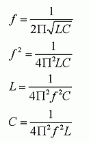
f is the frequency (Hertz)
-
C is the capacitance (Farads)
-
L is the inductance (Henrys)
-
The Resonant Frequency f0 = 1 / ( 2 π √( L C ) )
-
Dynamic Resistance RD = L / ( RL C ) RL is the DC resistance of the inductor assuming any other resistances in the tuned circuit are negligible.
-
At resonance, an ideal tuned circuit has an infinite dynamic resistance.
-
In real life RD is less due to energy losses, mostly in the inductor.
-
Capacitor energy losses are smaller and often ignored.
-
At resonance Xc = XL
-
Xc = 1 / ( 2 π f0 C )
-
XL = 2 π f0 L
-
1 / ( 2 π f0 C ) = 2 π f L
-
f02 = 1 / ( 4 π2 LC )
-
The capacitor is often variable for radio tuning.
-
The inductor sometimes has a ferrite or iron core.
-
Variable inductors can be used too. These contain a ferrite slug that can be screwed into to the centre of the coil.
Tuned circuits work like this ...
-
Energy is stored in the capacitor in the form of electric charge
-
Energy is also stored in the inductor in the form of a magnetic field
-
When the capacitor is fully charged, there is no current in the inductor
-
When the capacitor is fully charged, the potential difference across the circuit is at its maximum
-
The potential difference will cause a current to flow in the inductor
-
When the current reaches its maximum value, the potential difference across the circuit falls to zero. At this time the magnetic energy stored in the inductor is at its maximum.
-
The stored magnetic energy causes the current to continue to flow.
-
This current re-charges the capacitor (with opposite polarity).
-
When the current falls to zero, the capacitor charge reaches its maximum value.
-
This current continues to oscillate back and forth until it dies away due to energy losses.
-
An active device such as a field effect transistor can be used boost the energy causing continuous oscillation.
Here is a water analogy.
-
The maximum water level difference occurs at the same moment as the minimum water flow.
-
The maximum water flow occurs when the water is level and there is no pressure difference between the ends of the bath.
-
The water pressure and the water flow are 90 degrees out of phase.
-
The same thing happens with the current and voltage in a tuned circuit and a radio antenna.
Tuned Circuit Animation
Ferrite Rod Tuned Circuit
Note the small variable capacitor and thin coil wire used for low receiver voltages.
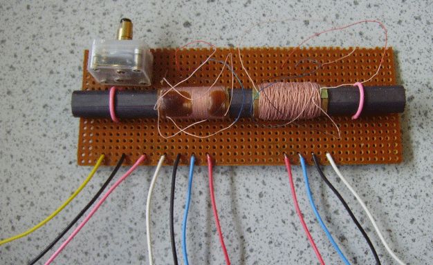
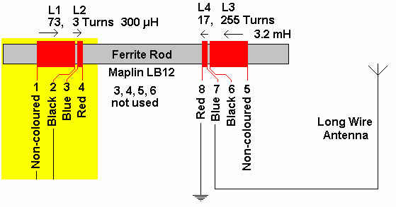
This doubles up as the antenna and tuned circuit in low cost radio receivers designed for the long wave (LF) and medium wave (MF) bands.
The addition of the ferrite greatly increases the inductance of the coils. This reduces the resonant frequency.
Ceramic Resonators and Quartz Crystals
These devices also exhibit strong resonant behaviour. They can be used in filter circuits and oscillators replacing the conventional tuned circuit. The advantages are small size, low cost and a high Q factor. However they can't be tuned like an L C circuit.
Inductors can be BIG

Subject Name
Level
Topic Name
Question Heading
First Name
Last Name Class ID
User ID
Question Text
image url
Help Link
Add
Delete
Clone
Edit
Hardness
Help Text
Debug
- You can attempt a question as many times as you like.
- If you are logged in, your first attempt, each day, is logged.
- To improve your scores, come back on future days, log in and re-do the questions that caused you problems.
- If you are logged in, your most recent wrong answers get remembered. This might help you and your teacher to correct your understanding.
- In the grade book, you can delete your answers for a topic before re-doing the questions. Avoid deleting unless you intend re-doing the questions very soon.
