 Home
Home
rOm
Quest
Glossary
Random
Page
Search
Site
Lush
Sim
Class
Subject
Images
Help
FAQ
Sign
Up
Log
In
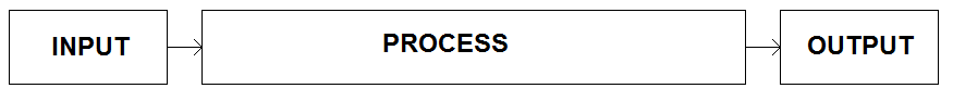
Complex electronic systems can be broken down into simpler sub-systems. This makes it easier to understand, design and test the circuits.
Systems typically have ...
-
INPUT/S - Sensing
-
Light,
-
Temperature
-
Magnetic field
-
Pressure
-
Moisture
-
Sound
-
Movement or Rotation
-
PROCESS/ES
-
Comparator
-
Logic gates
-
Latch
-
Time delay
-
A to D Converter
-
D to A Converter
-
Microcontroller
-
OUTPUT/S
-
Lamp or LED
-
Warning buzzer
-
Solenoid
-
Actuator, Motor or Servo
-
Loudspeaker
-
Most output transducers need a DRIVER.
Sub-systems and System Diagrams (Labelled boxes joined with arrows)
System diagrams are used to describe systems and sub-systems.
Dividing a system into sub-systems is a good idea because a whole system can be hard to understand.
Each sub-system can be quite simple.
Complex systems are only possible because different teams of designers and testers are responsible for each sub-system.
Many sub-systems can be purchased pre-built and tested.
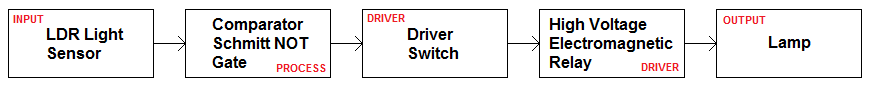
Example: Turn on a lamp when it gets dark.
To achieve this you'd need ...
-
A light sensor in a voltage divider circuit.
-
A comparator to sense when the light sensor detects it's too dark
-
A driver because the comparator is not able to drive the relay without some help.
-
An electromagnetic relay because this can switch high voltage AC mains.
-
A lamp
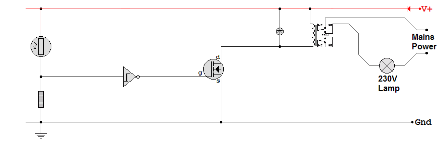
Circuit Diagram (Don't confuse circuit and system diagrams)
-
It's possible to design and test each sub-system on its own.
-
Frequently needed sub-systems like the relay are mass produced at low cost.
-
The same sub-systems can often be used to solve many different problems.
A More Complex Example
-
Decoupling Capacitor
-
Voltage Divider - a fixed reference voltage
-
Voltage Divider - a light dependent voltage that decreases as it gets dark
-
Op Amp Comparator. In daylight, the output is LOW. At night, the output is HIGH.
-
555 Astable. At night, the reset pin is HIGH and the astable oscillates causing the lamp to flash. In daylight, reset is LOW and the lamp is OFF.
-
Transistor Switch Transducer Driver. The transducer is the lamp.
Subject Name
Level
Topic Name
Question Heading
First Name
Last Name Class ID
User ID
Question Text
image url
Help Link
Add
Delete
Clone
Edit
Hardness
Help Text
Debug
- You can attempt a question as many times as you like.
- If you are logged in, your first attempt, each day, is logged.
- To improve your scores, come back on future days, log in and re-do the questions that caused you problems.
- If you are logged in, your most recent wrong answers get remembered. This might help you and your teacher to correct your understanding.
- In the grade book, you can delete your answers for a topic before re-doing the questions. Avoid deleting unless you intend re-doing the questions very soon.