WANTED: Individual or team to take over this project. I'm in my 70's and want to put my feet up. Contact details in footer.
| A Level >Logic< Tristate |
Logic |
|
Logic Gates are digital switching circuits that obey simple rules.
The inputs and outputs are LOW ( 0 ) or HIGH ( 1 ) and should never float halfway between.
A LOW signal is a voltage less than half the power supply, usually close to zero.
A HIGH signal is a voltage more than half the power supply, usually close to five volts ( or 3.3V in low voltage logic ).
Never leave inputs unconnected. They float, act as an antenna, and pick up every noise signal in range.
| AND | NAND | OR | NOR | XOR | XNOR | NOT | ||||||||||||||||||||||||||||||||||||||||||||||||||||||||||||
|
|
|
|
|
|
  |
|
||||||||||||||||||||||||||||||||||||||||||||||||||||||||||||
|
Two ones give a one. Anything else gives 0. |
Two ones give a 0. Anything else gives 1. |
Two zeros give a 0. Anything else gives 1. |
Two zeros give a 1. Anything else gives 0. |
Equal inputs give a 0. | Equal inputs give a 1. | Input is inverted. | ||||||||||||||||||||||||||||||||||||||||||||||||||||||||||||
A B   Q
0 0   0
0 1   0
1 0   0
1 1   1
|
A B   Q
0 0   1
0 1   1
1 0   1
1 1   0
|
A B   Q
0 0   0
0 1   1
1 0   1
1 1   1
|
A B   Q
0 0   1
0 1   0
1 0   0
1 1   0
|
A B Q 0 0 0 0 1 1 1 0 1 1 1 0 |
A B Q 0 0 1 0 1 0 1 0 0 1 1 1 |
A Q 0 1 1 0 |
||||||||||||||||||||||||||||||||||||||||||||||||||||||||||||
|
|
|
|
|
|
|
| CMOS 4000 Series Chips | TTL 7400 Series Chips | Commonly Used Terms | |
| Technology | Complementary Metal Oxide Semiconductor | Transistor Transistor Logic | |
| LOW | A voltage less than 0.5 of the power supply | 0 to 0.8 V | 0, Zero, Off, Clear, False |
| HIGH | A voltage greater than 0.5 of the power supply | 2.2 to 5 V | 1, One, On, Set, True |
| Power | Extremely low power consumption | High power use compared with CMOS | |
| Speed | Slower | Faster |
BOOLE: A mathematician called Boole invented a branch of maths for processing true and false values instead of numbers. This is called Boolean Algebra. Simple Boolean algebra is consistent with common sense but if you need to process decisions involving many values that might be true or false according to complex rules, you need this branch of mathematics. Boolean algebra was invented long before the invention of logic gates!
There are several types of gate. Each follows a very simple set of rules. By combining many gates in suitable ways, processing devices can be produced. A computer CPU chip can have millions of gates fabricated onto it. The table above shows several gates with two inputs. Many of these gates are also available in three, four and eight input versions.
Computers work using LOGIC. Displaying graphics such as the mouse cursor involves the XOR (Exclusive OR) operation. Arithmetic addition makes use of AND and XOR.
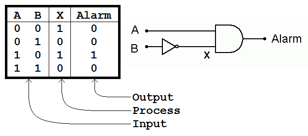
The one line descriptions of the rules above are clearer if shown in Truth Tables. These tables show the output for all possible input conditions. The inputs are always listed in the same order (counting in binary starting from zero).
EXAMPLE: There are two inputs, A and B. Input B is inverted by the NOT gate to give X.
If A and X are both high the AND gate output will go high and the alarm will sound.
This is one of the simplest logic circuits that does something useful. It adds two bits together.
A      B   C  S
0 plus 0 = 0  0
0 plus 1 = 0  1
1 plus 0 = 0  1
1 plus 1 = 1  0
Subject Name Level Topic Name Question Heading First Name Last Name Class ID User ID
|
Q: qNum of last_q Q ID: Question ID Score: num correct/num attempts Date Done
|
Question Text
image url
Help Link
Add Delete Clone Edit Hardness
Contact, Copyright, Cookies and Legalities: C Neil Bauers - reviseOmatic V4 - © 2016 to 2026
Hosted at Akamai Cloud - London
Please report website problems to Neil