Site Logo Home
 
rOm
Quest
Glossary
 
Random
Page
Search
Site
Lush
Sim
Class
Subject
Images
 
Help
FAQ
Sign
Up
Log
In
GCSE     Resistors     BS1852     Colour Codes     E24     LDR     Parallel     PIVR Calculations     Potentiometer     Puzzles     Series     Thermistor     Timing     Types     >Voltage Divider<    

Resistors Voltage Divider


Site for Eduqas/WJEC - Go to the AQA site.

  GCSE    Resistors  0 of 27    Question 1372    BS1852 Resistors 
Score 0/0 
Not attempted  
Last Answer  
Deadline not set1 of 27    Question 1371    BS1852 Resistors 
Score 0/0 
Not attempted  
Last Answer  
Deadline not set2 of 27    Question 1373    BS1852 Resistors 
Score 0/0 
Not attempted  
Last Answer  
Deadline not set3 of 27    Question 1368    Colour Codes 
Score 0/0 
Not attempted  
Last Answer  
Deadline not set4 of 27    Question 1367    Colour Codes 
Score 0/0 
Not attempted  
Last Answer  
Deadline not set5 of 27    Question 1366    Colour Codes 
Score 0/0 
Not attempted  
Last Answer  
Deadline not set6 of 27    Question 1500    Components 
Score 0/0 
Not attempted  
Last Answer  
Deadline not set7 of 27    Question 275    Components 
Score 0/0 
Not attempted  
Last Answer  
Deadline not set8 of 27    Question 269    Components 
Score 0/0 
Not attempted  
Last Answer  
Deadline not set9 of 27    Question 244    Components 
Score 0/0 
Not attempted  
Last Answer  
Deadline not set10 of 27    Question 243    Components 
Score 0/0 
Not attempted  
Last Answer  
Deadline not set11 of 27    Question 242    Components 
Score 0/0 
Not attempted  
Last Answer  
Deadline not set12 of 27    Question 1445    Components 
Score 0/0 
Not attempted  
Last Answer  
Deadline not set13 of 27    Question 1376    E24 
Score 0/0 
Not attempted  
Last Answer  
Deadline not set14 of 27    Question 1375    E24 
Score 0/0 
Not attempted  
Last Answer  
Deadline not set15 of 27    Question 1425    Identify the Component 
Score 0/0 
Not attempted  
Last Answer  
Deadline not set16 of 27    Question 1424    Identify the Component 
Score 0/0 
Not attempted  
Last Answer  
Deadline not set17 of 27    Question 1426    Identify the Component 
Score 0/0 
Not attempted  
Last Answer  
Deadline not set18 of 27    Question 438    Ohm's Law and Current Calculations 
Score 0/0 
Not attempted  
Last Answer  
Deadline not set19 of 27    Question 160    Ohms Law 
Score 0/0 
Not attempted  
Last Answer  
Deadline not set20 of 27    Question 162    Ohms Law 
Score 0/0 
Not attempted  
Last Answer  
Deadline not set21 of 27    Question 561    Resistors 
Score 0/0 
Not attempted  
Last Answer  
Deadline not set22 of 27    Question 2    Resistors in Parallel 
Score 0/0 
Not attempted  
Last Answer  
Deadline not set23 of 27    Question 178    Resistors in Series 
Score 0/0 
Not attempted  
Last Answer  
Deadline not set24 of 27    Question 526    Thermistors 
Score 0/0 
Not attempted  
Last Answer  
Deadline not set25 of 27    Question 525    Thermistors 
Score 0/0 
Not attempted  
Last Answer  
Deadline not set26 of 27    Question 524    Thermistors 
Score 0/0 
Not attempted  
Last Answer  
Deadline not set27 of 27    Question 523    Thermistors 
Score 0/0 
Not attempted  
Last Answer  
Deadline not set  Questions 0 to 27   -->  View All  

This circuit divides the voltage in the same ratio as the resistors so V1 / V2   =   R1 / R2   and   V2   =  Vs R2 / (R1 + R2)    where Vs is the supply voltage.

Voltage Divider        Light Sensor Driver and Lamp

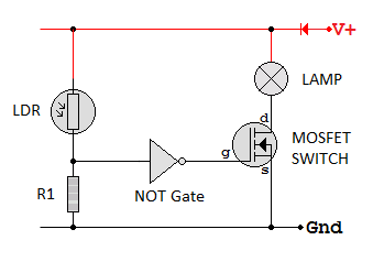
R1 and R2 form a Voltage Divider. Usually one of these is variable and used to sense light, temperature, position, pressure etc.

The light sensing circuit turns on the lamp when it gets dark. A Schmitt trigger NOT gate should be used.

The voltage is divided in the ratio of the resistor values (assuming the current is the same in both resistors).

Two or more resistors in series can be used to set a required voltage at a point in a circuit. For example, this could correspond to

V2 = Vs R2 / (R1 + R2)    where Vs is the supply voltage.

V1 = Vs R1/ (R1 + R2)    where Vs is the supply voltage.

V1 / R1 = V2 / R2        or        V1 / V2 = R1 / R2        also        V1 + V2 = Vs

In this simulation, the resistors add up to 12kΩ and the voltage is 12 Volts.
This makes the maths stupidly simple.
Each "k" of resistance has one volt across it. Simples!
Click the switch to turn on the circuit.

Subject Name     Level     Topic Name     Question Heading     First Name Last Name Class ID     User ID    

fff
Home
<<<
ppw
Pg Up
<<
ppp
Up
<
|||

>|<
nnn
Down
>
nnw
Pg Down
>>
lll
End
>>>

Close
Escape
X

Q: qNum of last_q     Q ID: Question ID         Score: num correct/num attempts         Date Done    


Submit
Enter


Question Text

image url


Help Link

Add     Delete     Clone     Edit     Hardness

Help Text
Debug


Contact, Copyright, Cookies and Legalities: C Neil Bauers - reviseOmatic V4 - © 2016/17

Hosted at linode.com - London


Please report website problems to Neil