 Home
Home
rOm
Quest
Glossary
Random
Page
Search
Site
Lush
Sim
Class
Subject
Images
Help
FAQ
Sign
Up
Log
In
WANTED: Individual or team to take over this project. I'm in my 70's and want to put my feet up. Contact details in footer.
Basics
-
If charge accelerates, electromagnetic radiation is produced. In an antenna repeatedly reversing the current flow, creates the acceleration and radiation.
-
A receiving antenna converts electromagnetic radiation (radio waves) into an alternating current or voltage.
-
A transmitting antenna converts an alternating current and voltage into electromagnetic radiation (radio waves).
-
An antenna is a transducer designed to transmit or receive electromagnetic energy (radio waves) to or from the medium of free space.
-
Antennas are designed to do this as efficiently as possible.
-
A good transmitting antenna will also be a good receiving antenna.
Half Wave Dipole Antenna
-
One of the most commonly used antennas.
-
It is half a wavelength long.
-
This antenna works best when the waves arrive broadside.
-
End-on the antenna is very inefficient.
-
The height of the antenna above the ground makes a big difference to the vertical angle of the radiated or received energy.
-
A horizontal dipole antenna near the ground sends a large part of it's energy vertically upwards. This is ideal for local radio transmissions where the signal bounces off the ionosphere above the transmitter and returns to earth locally. This works for MF and HF transmissions but not VHF and above.
-
If the horizontal dipole antenna is placed half a wavelength above the ground, the vertical radiation cancels out with the radiation reflected off the ground. Much less energy goes straight up and more energy radiates at lower angles. This is better for long distance communication reflected off the ionosphere at lower angles.
Wavelength and Frequency
-
Wavelength - the length in metres of one complete cycle of the wave.
-
Frequency - the number of cycles per second of the wave measured in Hertz.
This gives a feel for what happens in an antenna. In the animation, the electron movement is greatly exaggerated. In real life, each electron moves fractions of a millimetre but there are huge numbers of electrons moving.
Antenna Calculations
Calculating Wavelength and the Length of a Dipole
C = F λ
C is the speed of light = 300 000 000 metres per second (3x10⁸).
F is the frequency - for example 100 MHz (the FM radio band in the UK)
λ is the wavelength. This is the Greek letter Lambda.
λ = C / F
λ = 300 000 000 / 100 000 000 = 3 Metres wavelength.
The half wave dipole will be 1.5 metres long for the 100MHz FM radio band.
Electromagnetic Waves
This diagram shows the electric and magnetic components at right angles to each other and in phase. The electromagnetic radiation is produced by the acceleration of charge. The dipole antenna used to radiate this would also be vertical.
-
Radio waves have an alternating electric field and an alternating magnetic field. This is why they are called electromagnetic waves.
-
Polarisation can be vertical, horizontal or circular.
-
This refers to the electric field component of the wave.
-
Antennas must be oriented correctly to receive horizontal or vertical signals.
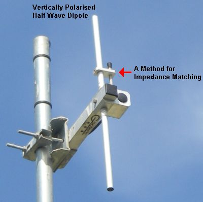
FM Radio Polarisation
A vertical car radio antenna will receive vertically polarised waves best. In fact the FM band transmissions use circular polarisation so the antenna orientation does not matter.
Some TV transmissions are horizontal and some are vertical. This allows regional transmitters to be placed closer together because a vertically polarised transmitter will not interfere with horizontally polarised antennas.
Impedance Matching
The antenna impedance must match the feeder cable impedance.
-
For example a 75Ω antenna should be connected to a 75Ω cable.
-
For example a 50Ω antenna should be connected to a 50Ω cable.
When the impedance is matched ...
-
a transmitting antenna radiates the most electromagnetic energy
-
a receiving antenna picks up the most electromagnetic energy
-
minimal energy is lost as heat
-
very little radiation is reflected back from the antenna to the transmitter
 UHF Radio Controlled Orange Orchard Irrigation
Dipole Antenna Impedance
Measure the voltage and current at the feed point (where the co-axial cable is connected).
-
In the diagram above, the impedance is low at the centre of the dipole.
-
There is a low voltage and a high current.
-
At the ends of the dipole, the current is low - it's a dead end.
-
The voltage here is high. This gives a high impedance.
-
Ohm's law is used to calculate the Impedance.
The result will be about 50 or 75 Ohms depending on the antenna and the type of co-axial cable.
Similar measurements can be made along the co-axial cable. If a matched cable is being used, the result will be about 50 or 75 Ohms.
If the wrong type of cable is used ...
-
the antenna works less efficiently
-
instead of being transmitted, a proportion of the waves are reflected back to the transmitter
-
energy is lost as heat in the feeder cable
-
energy is lost as heat in the transmitter
-
in an extreme case the transmitter or feed cable could be damaged by overheating
-
there will be standing waves on the feeder cable giving zones where the voltage or current is greater than normal
-
the high voltage zones can cause insulation breakdown if the transmitter power is high enough
-
a standing wave ratio (SWR) meter can be used to check the impedance matching. This measures the forward and reflected currents. The aim is to make the reflected current as close to zero as possible.
-
with receiving antennas, the same problems apply but the energies are too small for the heating and voltage effects to be noticed. The antenna just works badly.
Other Impedance Matching Examples
-
Computer SCSI disk cables need to be terminated.
-
This prevents the reflection of digital pulses from the end of the cable.
-
Computer RAM memory RIMMs must be terminated.
-
This is a computer memory technology. Again, reflected pulses are prevented.
-
Some computer networks use co-axial cable (an obsolete technology). These cables must be terminated. This prevents the reflection of digital pulses from the ends of the cable.
-
Sea defences use large rocks to soak up the energy of the arriving waves. These defences also reduce the reflection of the waves.
-
River entrances used for shipping have designed beach and rock areas to prevent waves radiating up the river.
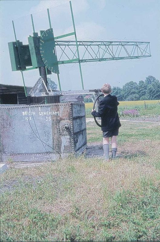
Satellite Tracking
A circularly polarised small-boy-steerable antenna for satellite tracking in the 136 - 138 MHz VHF satellite band. This was used at Douai School to receive weather pictures from one of the low earth orbit satellites in around 1970. I believe this school was the first UK site to decode the weather pictures, even beating the Met' Office.
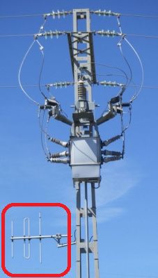
Yagi Antenna
These are based on the half wave dipole but the other elements make the antenna directional. In the forward direction, they work much better than a dipole. In other directions they are much less efficient than a dipole. The connection of the co-axial cable is usually more complex than shown to maximise the transfer of energy from the antenna to the feeder cable.
And here is a vertically polarised Yagi antenna used for remote power line switching. This antenna is quite directional. It works better in the wanted direction as well as rejecting signals from the wrong direction.
Quarter Wave "Vertical" Antenna
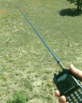
This antenna is a quarter of a wavelength long and is often vertical. The antenna relies on a mirror effect to work. Here the mirror is the users own body. This is safe for low powers. Metal car bodies work well and for large antennas, the earth itself. The antenna and the mirror image behave very like a half wave dipole. Telescopic radio aerials work on this principle. For example a car's aerial will be about a quarter wave long and the car body acts as the earth to provide the mirror image. For the 100 MHz FM radio band, the antenna will be about 75 cm long and a bit shorter for DAB radio.
Rubber Duck
The antenna is coiled and encased in rubber. It's springy and bendy. It behaves as a quarter wave but the coiling means it takes up less space. It's a bit less efficient than a straight wire quarter wave.
Subject Name
Level
Topic Name
Question Heading
First Name
Last Name Class ID
User ID
Question Text
image url
Help Link
Add
Delete
Clone
Edit
Hardness
Help Text
Debug
- You can attempt a question as many times as you like.
- If you are logged in, your first attempt, each day, is logged.
- To improve your scores, come back on future days, log in and re-do the questions that caused you problems.
- If you are logged in, your most recent wrong answers get remembered. This might help you and your teacher to correct your understanding.
- In the grade book, you can delete your answers for a topic before re-doing the questions. Avoid deleting unless you intend re-doing the questions very soon.