RANDOM PAGE
SITE SEARCH
LOG
IN
SIGN UP
HELP
To gain access to revision questions, please sign up and log in.
A2
Flash ADC
High speed conversion of an analogue signal into a digital signal.
- Used with Video signals.
- Not needed with slower signals like Audio and human interface devices.
Advantages |
Disadvantages |
- Fast because the speed is limited only by the comparators and exclusive or gates.
- Suitable for digitising video because of its speed
- Fairly easy to understand because it only requires comparators, exclusive OR gates and diodes (used as OR gates).
|
- Expensive
- High component count (not too much of a problem with custom designed ICs).
- Very hard to build from discrete components because of the large number of components needed.
|
To calculate the resolution of the ADC ...
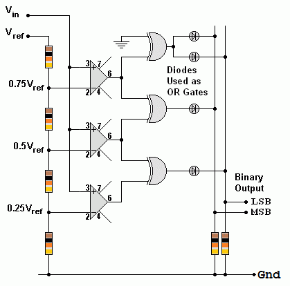
- The ADC below detects four different input levels
- The resolution is Vref / 4
- An 8 bit ADC can resolve 28 levels = 256 levels so the resolution is Vref / 256
To calculate the number of comparators (or exclusive OR gates) needed ...
- 2N - 1 comparators are needed where N is the number of bits in the output.
- In the example below, there is a two bit output so 22 - 1 = 3 comparators needed.
- For a four bit converter, 24 - 1 = 15 comparators needed.
- For an 8 bit converter, 28 - 1 = 255 comparators needed. (hard to implement)
- For a 16 bit converter, 216 - 1 = 65535 comparators needed. (Some CPU processors have millions of gates so this is entirely possible.)
For the Falstad Circuit Simulation, CTRL+Click Flash ADC
In options, check European Resistors and uncheck Conventional Current.
Adjust the slider to change the analogue input voltage.
Alternatively view A_to_D_Flash.txt.
Save or copy the text on the web page. Import the saved or copied text into the Falstad simulator.
Here is the new HTML5 Simulator Site.

This is a two bit flash ADC (not very useful!) 8 or 16 bits would be much more use but also very much more complex.
- The circuit above has three comparators.
- Each comparator is fed a proportion of the reference voltage from Vref.
- If the input voltage (Vin) is too low, all the comparators will be turned off.
- If Vin is a little higher, only the bottom comparator will turn on.
- If Vin is a little high still, the bottom two comparators will turn on.
- If Vin is high enough, all the comparators will turn on.
- If all the comparators are off, the output will be 0 0. This is zero in binary.
- If the bottom comparator is on, the output will be 0 1. This is one in binary.
- If the bottom two comparators are on, the output will be 1 0. This is two in binary.
- If all the comparators are on, the output will be 1 1. This is three in binary.
- Adding extra bits is simple. More comparators are needed and the output logic gets more complex too.
Look here for a very similar three bit comparator that has about double the component count. Each extra bit added doubles the component count again. An 8 bit converter would need 255 comparators and exclusive or gates.
Half Flash ADC
An 8 bit converter would need 28 - 1 comparators = 255. This complexity makes the chip expensive and more difficult to make.
With some loss of speed, it's possible to use two 4 bit flash converters with some additional circuitry. This is the circuit diagram.

- The analogue input is converted using the first 4 bit Flash ADC.
- This gives an approximate binary value ( bits 4, 5, 6 and 7 ) which is converted back into an analogue voltage by the DAC.
- This approximate value is subtracted from the original signal and what's left is converted to digital by the second Flash ADC ( bits 0, 1, 2 and 3 ).
- This 8 bit value is stored in the latch when the clock line goes high.
- Due to the time delay introduced by the extra circuitry, a sample and hold circuit on the input would be essential.
reviseOmatic V3
Contacts, ©, Cookies, Data Protection and Disclaimers
Hosted at linode.com, London


