
Sample and Hold Circuit |
|
To gain access to revision questions, please sign up and log in.

Sample and Hold circuits are used to "remember" an analogue voltage for a time period long enough to process the sample. For example if an analogue signal is being converted to digital, the signal must be held for the duration of the conversion.
The simplest circuit could be a single capacitor. This would be satisfactory if there was no capacitor leakage current and the ADC input had a very high input resistance. In addition, there would need to be a way to disconnect the input while the sample was being held.
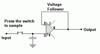
A better solution is to use a capacitor with a voltage follower. The voltage follower has the required high input resistance and it can drive the ADC input which need not have a high input resistance.
While the switch is open, the capacitor voltage will remain constant assuming there is no leakage current through the capacitor or the op' amp'.
When the switch is closed, the capacitor will rapidly charge to match the input voltage.
For a real life application, the input switch needs to be digitally controlled.
Analogue Switch chips are available. While active, the switch is closed. In the "off" state, the analogue chip has a high output resistance. This effectively disconnects the analogue switch. This ability to disconnect is similar to tristate logic chips which do the same thing.
The CD4066B chip is suitable. It contains four analogue switches. When active, the input is copied to the output. When disabled, the leakage current is about 10 pA (pico-amps).
reviseOmatic V3 Contacts, ©, Cookies, Data Protection and Disclaimers Hosted at linode.com, London