
RANDOM PAGE
SITE SEARCH
LOG
IN
SIGN UP
HELP
To gain access to revision questions, please sign up and log in.
A2
Flash LEDs in Sequence
|
CTRL+Click here to run the simulator.
- Type in the code below or copy and paste it.
- Click the "A" button to assemble the code (translate it into binary).
- Click the "S" button to step through the program.
- Connect the LEDs to PORTB and run this example program.
;===CONNECT LEDs TO PORTB===
INIT:
    MOVW    0x00    ; Eight Outputs
    MOVWR   TRISB   ; Data direction

START:
    MOVW    0x55    ; Control data
    MOVWR   PORTB   ; Write to port
    NOP             ; Get timing right
    NOP

    MOVW    0xAA    ; Control data
    MOVWR   PORTB   ; Write to port

    JMP     START
|
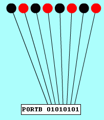
TASK: Alter the program to repeatedly flash each LED in turn going from right to left.
|
Design Traffic Lights Data
|
CTRL+Click here to run the simulator.
- Type in the code below or copy and paste it.
- Click the "A" button to assemble the code (translate it into binary).
- Click the "S" button to step through the program.
- Connect the Traffic Lights to PORTC and run this example program.
;   CONNECT TRAFFIC LIGHTS TO PORTC
    MOVW    0x00    ; Eight outputs
    MOVWR   TRISC   ; Data direction
START:
    MOVW    0x55    ; This number is wrong
    MOVWR   PORTC   ; Write control data
    NOP             ; Get timing right
    NOP

    MOVW    0xA     ; This number is wrong
    MOVWR   PORTC   ; Write control data
    NOP             ; Get timing right
    NOP

    MOVW    0xC     ; This number is wrong
    MOVWR   PORTC   ; Write control data
    NOP             ; Get timing right
    NOP

    MOVW    0x2     ; This number is wrong
    MOVWR   PORTC   ; Write control data

    JMP     START
|
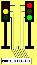
TASK: Design corrected control data for the traffic lights. Test your data.
|
Closed Loop Heater and Thermostat
|
CTRL+Click here to run the simulator.
- Type in the code below or copy and paste it.
- Click the "A" button to assemble the code (translate it into binary).
- Click the "S" button to step through the program.
- Connect the heater to PORTA and run this incomplete example program.
; ===== CONNECT THE HEATER TO PORTA =====
        MOVW    0X1     ; OOOOOOOI
        MOVWR   TRISA   ; SET PORTA I/O
LOOP:
        MOVRW   PORTA   ; READ HEATER PORT
        ANDW    0x1     ; IGNORE BITS 2 TO 7
        SUBW    0x1     ; SEE IF W CONTAINED 1
        JPZ     TOOHOT
        JMP     TOOCOLD

TOOHOT:
; ===== Add two lines here ==============
                        ; HEATER OFF
                        ; WRITE TO HEATER
        JMP     LOOP

TOOCOLD:
; ===== Add two lines here ==============
                        ; HEATER ON
                        ; WRITE TO HEATER
        JMP     LOOP
|
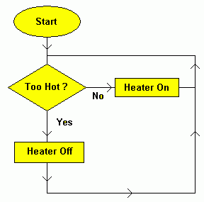
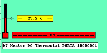
TASK: Complete the four missing lines to turn the heater on and off. |
Seven Segment Display
|
CTRL+Click here to run the simulator.
- Type in the code below or copy and paste it.
- Click the "A" button to assemble the code (translate it into binary).
- Click the "S" button to step through the program.
- Connect the Seven Segment Display to PORTC.
; ===== CONNECT THE DISPLAYS TO PORTC =====
    MOVW    0X00   ; SET 8 PORTC OUTPUTS
    MOVWR   TRISC  ; SET 8 PORTC OUTPUTS
    MOVWR   PORTC  ; CLEAR RIGHT SEGMENTS
    MOVW    0X80   ; CLEAR LEFT SEGMENTS
    MOVWR   PORTC  ; CLEAR LEFT SEGMENTS
START:
    MOVW    0X05
    MOVWR   PORTC
    MOVW    0X85
    MOVWR   PORTC

    MOVW    0X0
    MOVWR   PORTC
    MOVW    0X80
    MOVWR   PORTC

    JMP     START
|
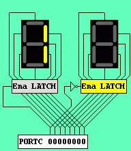
TASK: Count from 0 to 9 (Easy).
TASK: Count from 00 to 99 (Very Hard).
|
H-Bridge Controller
|
CTRL+Click here to run the simulator.
- Type in the code below or copy and paste it.
- Click the "A" button to assemble the code (translate it into binary).
- Click the "S" button to step through the program.
- Connect the Switches to PORTB.
- Connect the H-Bridge Controller to PORTB.
; ===========================================
;       H  Bridge  Motor  Control
;       CONNECT  HBRIDGE TO PORTB
;       CONNECT SWITCHES TO PORTB
; ===========================================
        MOVW    0XF0    ; 4 Inputs & Outputs
        MOVWR   TRISB   ; Set PORTB direction
START:
        MOVRW   PORTB   ; READ PORTB
        ANDW    0X70    ; BIT MASK
        SUBW    0X10    ; TEST S4 CLOSED
        JPZ     FORWARD ; Jump If Closed

        JMP     COAST   ; Freewheel
; ===========================================
FORWARD:
        MOVW    0X09    ; Close bits 0 and 3
        MOVWR   PORTB
        JMP     START
; ===========================================
COAST:
        MOVW    0X0     ; Open all switches
        MOVWR   PORTB
        JMP     START
; ===========================================
|
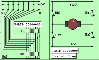
TASK: Get the motor to run in either direction.
TASK: Set the switches to get a braking effect.
|
Gray Code Position Control
CTRL+Click here to run the simulator.
- Type in the code below or copy and paste it.
- Click the "A" button to assemble the code (translate it into binary).
- Click the "S" button to step through the program.
- Connect the Gray Code Controller to PORTC.
- Run the program at a high clock rate or the mechanism will overshoot.

; ================================
; ===== GRAY CODE CONTROLLER =====
; ================================
    MOVW    0X3F    ; OOIIIIII
    MOVWR   TRISC   ; Data direction

FORWARD:
    MOVW    0X40    ; Set bit 6
    MOVWR   PORTC   ; Go right
F_REP:
    MOVRW   PORTC   ; POLL PORTC
    ANDW    0X3F    ; Bit Mask
    SUBW    0X0F    ; Position test
    JPZ     BACKWARD; Position found
    JMP     F_REP   ; Position not found

BACKWARD:
    MOVW    0X80    ; Set bit 7
    MOVWR   PORTC   ; Go left
B_REP:
    MOVRW   PORTC   ; POLL PORTC
    ANDW    0X3F    ; Bit mask
    SUBW    0X03    ; Position test
    JPZ     FORWARD ; Position found
    JMP     B_REP   ; Position not found
TASK: Get it to reverse if it overshoots and hits the end of the scale.
Stepper Motor
|
CTRL+Click here to run the simulator.
- Type in the code below or copy and paste it.
- Click the "A" button to assemble the code (translate it into binary).
- Click the "S" button to step through the program.
- Connect the Stepper Motor to PORTB.
; ====================================
; ===== CONNECT STEPPER TO PORTB =====
; ====================================
start:
    movw    0x1
    movwr   portb
    nop
    nop

    movw    0x2
    movwr   portb
    nop
    nop

    movw    0x4
    movwr   portb
    nop
    nop

    movw    0x8
    movwr   portb

    jmp     start
|
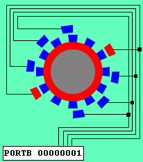
TASK: Make the motor run backwards.
TASK: Make the motor run in half steps.
|
Summing DAC
|
CTRL+Click here to run the simulator.
- Type in the code below or copy and paste it.
- Click the "A" button to assemble the code (translate it into binary).
- Click the "S" button to step through the program.
- Connect the Summing DAC PORTA.
; ================================
; ===== CONNECT DAC TO PORTA =====
; ================================
    movw    0x0
start:
    movwr   porta
    addw    0x1
    jmp     start
|
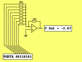
- The gain of the most significant bit input is one.
- The microcontroller digital output voltages are ...
- 0 Volts = Low.
- 5 Volts = High.
TASK: Work out the resolution (smallest step size) of this DAC.
TASK: Work out the values of the other input resistors.
TASK: How many output levels are available from this DAC.
|
Digital Ramp ADC
|
CTRL+Click here to run the simulator.
- Type in the code below or copy and paste it.
- Click the "A" button to assemble the code (translate it into binary).
- Click the "S" button to step through the program.
- Connect the ADC to PORTA.
; =============================
; = CONNECT RAMP ADC TO PORTA =
; =============================
        jmp     init
; ===== VARIABLES =====
count:  db      0x00
delay:  db      0x30
mask:   db      0x80
; =====================
init:
        movrw   mask
        movwr   trisa
        movw    0x0
        movwr   count
s:
        movrw   count
        movwr   porta
        movrw   porta
        andw    0x80
        jpz     pause
        inc     count
        jmp     s

pause:
        movrw    delay
rep:
        subw    0x1
        jpz     init
        jmp     rep
|
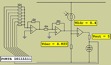
- The gain of the most significant bit input is one.
- The microcontroller digital output voltages are ...
- 0 Volts = Low.
- 5 Volts = High.
TASKS:
- What are the other resistor values?
- What is the resolution of this DAC?
- How many output values are possible?
- Why is the inverting amplifier needed?
- What is the function of the comparator?
- Why might the Zener diode be needed?
|
reviseOmatic V3
Contacts, ©, Cookies, Data Protection and Disclaimers
Hosted at linode.com, London


