RANDOM PAGE
SITE SEARCH
LOG
IN
SIGN UP
HELP
To gain access to revision questions, please sign up and log in.
A2
Long Wave (LF Band) Transmitter
Drop the frequency to 40kHz and try it with ultrasound transducers; it works but the bandwidth is too narrow for good quality voice or music. It's fine for PSK31 digital text.
- IMPORTANT: It is not legal to connect this circuit to an antenna.
- Even with an antenna which needs to be over 600 metres long, the power is so low that it's unlikely that anyone will notice.
- The transmitter works on about 220kHz. This can be picked up on a long wave radio.
- Check the 555 Astable frequency using an oscilloscope.
The 220pF capacitor might need to be decreased to get the frequency low enough to be heard on the long wave band.
- To receive the transmissions, place a long wave AM radio right next to the transmitter.


Design Goals
- Build a working AM transmitter using subsystems on the AQA specification.
- Simplicity rather than performance is the main goal.
Input Transducer
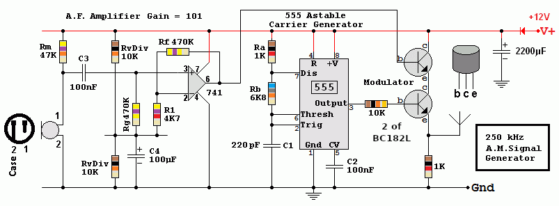
- This circuit is for voice transmissions so an Electret Microphone has been chosen.
- Rm provides DC power for the field effect transistor amplifier built into the microphone.
- Sound pressure waves cause the microphone current to vary in proportion. This causes the potential at C3 to vary.
- C3 is a coupling capacitor. It couples the audio from the microphone subsystem to the audio amplifier while blocking the DC potentials.
Non Inverting Amplifier
- The microphone provides 20 to 40 mV but the modulator needs 2 to 4 Volts.
- The non inverting amplifier has a gain = 1 + 470 / 4.7 = 101.
- The two resistors labelled RvDiv form a voltage divider with a 6 Volt output.
This allows the op amp to function without a negative power supply.
- C4 is a decoupling capacitor. It ensures that the 6 Volt DC level is steady without any AC signals present.
- Rg holds the non inverting input at 6 Volts DC without lowering the input impedance too much.
- Rf and R1 control the gain.
Carrier Generator
- As this transmitter works on such a low frequency, a 555 timer oscillator has been chosen for simplicity.
- Ra, Rb and C1 control the frequency. F = 1.44 / (( Ra + 2 Rb ) C1 )
- If you do the astable maths with the 220pF capacitor, it predicts the frequency will be just under 450 kHz.
In fact it's nearer 220kHz.
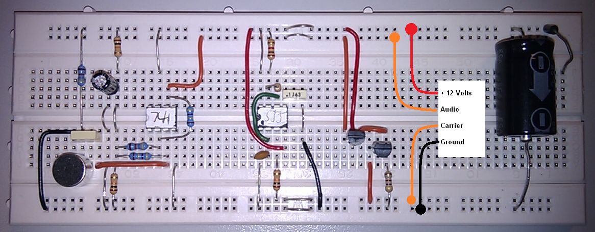
This is due to the stray capacitance of the prototype board resulting in a lower frequency.
- The carrier frequency control is poor. It drifts with temperature and changes in the power supply voltage. Warming the 555 chip with the heat from your finger produces a noticeable frequency drift. (Idea for a possible temperature sensor).
- The RC timing circuit and the 555 timer should be replaced with a quartz crystal oscillator.
- The 555 timer output is an approximate square wave.
This is a bad idea for a transmitter because harmonics (multiples) of the carrier frequency are also transmitted.
To fix this, a sine wave oscillator should be used for the carrier generator.
A further fix is to add a low pass filter to the antenna output. This blocks the transmission of the harmonics.
Modulator
- The modulator consists of two emitter followers.
- The bottom transistor is switched by the signal from the 555 timer.
- The top transistor is connected as an emitter follower and it varies the supply voltage for the bottom transistor.
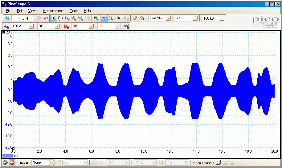
This varies the amplitude of the output carrier.
- The input to the top emitter follower comes from the audio amplifier. Hence the audio signal controls the amplitude of the RF signal.
- The Amplitude Modulator is rather basic but it works although the audio is somewhat distorted.
The Output

Ultrasound Version
Most ultrasonic transducers work best at about 40kHz but have a bandwidth of only one kilohertz. For voice AM, a bandwidth of at least 6kHz and preferably 10kHz is needed. The inadequate bandwidth results in muffled audio with the higher frequencies missing. Acceptable performance is possible by deliberately de-tuning the transmitter.
For digital text modes like BPSK31, the ultrasound transducers are ideal.
reviseOmatic V3
Contacts, ©, Cookies, Data Protection and Disclaimers
Hosted at linode.com, London


