
RANDOM PAGE
SITE SEARCH
LOG
IN
SIGN UP
HELP
To gain access to revision questions, please sign up and log in.
A2
aFrequency Modulation / VHF Broadcasting Band from 88 to 108 MHz
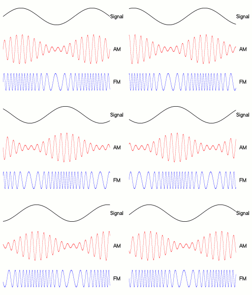
- FM transmitters vary the frequency of the carrier wave to broadcast programme content.
- The carrier frequency varies in proportion to the amplitude of the audio signal being modulated.
- A higher information signal frequency causes the carrier frequency to deviate at a greater rate.
- The amplitude of the carrier does not change.
bFM on a Picoscope
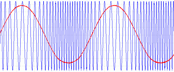
- The blue is the carrier.
- The red is the sound wave being modulated.
- Real life FM does not change the frequency so much and it would be hard to see on a trace like this.
cIncreasing the Audio Amplitude
- Here the frequency is deviating more from its unmodulated frequency.
- This would be caused by increasing the amplitude of the audio programme content.
dIncreasing the Audio Frequency
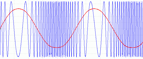
- The amplitude still has not changed.
- The frequency deviates more times per second, reflecting the higher frequency audio.
eAmplitude Noise Rejection
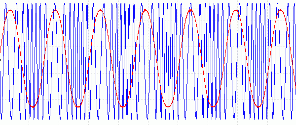
AM suffers badly from noise. FM suffers much less. Noise varies the amplitude of the received signal in a random way. It sounds like a hissing noise (waterfall) with additional cracks and pops caused by lightning strikes or electric circuit switching. AM radios can not reject these unwanted signals.
FM signals can be amplified so much that the amplifier limits. Any amplitude noise will be removed as long as the amplifier continues to limit. The frequency information is undamaged by this limiting. The FM demodulator comes after the limiting amplifier. This works extremely well as long as the FM signal is significantly stronger than the background noise in the receiver.
fFM Bandwidth and Deviation
- FM comes in two versions.
- NBFM is Narrow Band FM. This is for speech only transmissions such as ship to shore or short range walkie talkies. The bandwidth is similar to AM radio and the quality is good enough for speech.
- Broadband FM is used for high quality broadcast radio. The bandwidth is much greater and the sound quality is excellent too.
- FM modulation depth is a measure of how much the carrier deviates from its centre frequency for a given modulation input.
- Unlike AM there is no such thing as 100% modulation (unless the frequency deviates all the way to zero.)
- Excessive modulation causes the FM signal to overflow onto adjacent channels causing interference (similar to AM splatter).
gFM Bandwidth Calculation
Bandwidth = 2 x (deviation + fmax)
- deviation is the amount by which the carrier deviates either side of its centre frequency (+/- 75kHz for FM Radio)
- fmax is the highest frequency transmitted (music or voice - about 15 kHz on FM radio in the 100 MHz broadcast band)
- the VHF FM band goes from 88 to 108 MHz.
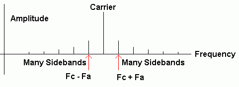
hFM Spectrum
- Fa is the Audio Frequency being modulated.
- Fc is the Carrier Frequency.
- For small carrier frequency deviations only the sidebands nearest the carrier are important. With larger frequency deviations, more sidebands are produced (an infinite number in theory but too small to detect further from the carrier frequency).
iFM Slope Demodulator
Demodulating FM properly is quite complex but the slope detector (demodulator) is simple enough to explain here.
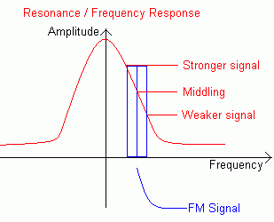
- When the FM signal deviates to a higher frequency, the tuned circuit responds less well and the output is lower.
- When the FM signal deviates to a lower frequency, the tuned circuit responds better and the output is greater.
- This effectively converts the FM to AM and an AM demodulator can be used.
This solution works but not well. The FM signal has to be de-tuned from the resonance point of the tuned circuit. If a stronger station is on the resonant frequency, the FM signal will be drowned out.
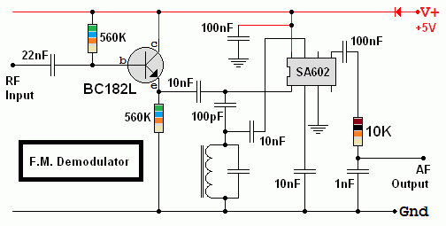
FM Demodulator - SA602 Chip
An untested design. The tuned circuit should be centered on the FM frequency to be received.
jFM Stereo
Stereo audio has two channels (left and right) and two loudspeakers are needed. This arrangement gives the illusion of space and sounds appear to be coming from the left, middle, right or anywhere in between. To record stereo, at least two microphones are needed.
FM stereo uses a simple frequency division multiplex system.
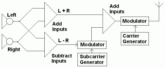
The left and right stereo channels are transmitted as a monophonic signal L+R using ordinary FM. A low cost monophonic receiver picks this up and demodulates the L+R transmission in the normal way.
The stereo information is modulated onto a 38 kHz sub-carrier. This is outside the range of human hearing so the simple radio (above) will not not produce a noticeable output. L-R is encoded onto the sub-carrier. A stereo receiver is designed to demodulate this signal as well as the conventional L+R FM signal.
To produce stereo ...
- a summing amplifier is used. It adds the conventional mono signal to the sub-carrier signal giving L+R.
- a differencing amplifier is used. It subtracts the conventional mono signal from the sub-carrier signal giving L-R.
kStereo Transmitter
lStereo Receiver

mDigital Frequency Shift Keying (FSK)
Binary zeros and ones are encoded as two slightly different carrier frequencies. This modulation scheme is very common on short wave radio bands where news agencies and business transmit text using FSK. It sounds like a very long and boring bird song.
reviseOmatic V3
Contacts, ©, Cookies, Data Protection and Disclaimers
Hosted at linode.com, London


