RANDOM PAGE
SITE SEARCH
LOG
IN
SIGN UP
HELP
To gain access to revision questions, please sign up and log in.
A2
aA Comparator with Different On and Off Voltages
bUses Positive Feedback
Here is a problem that the Schmitt trigger solves. You have built a circuit to turn on some lights when it gets dark. But when the lights turn on, it gets brighter so the lights go off again. But then it is too dark so they come on again - flashing on and off rapidly.
The Schmitt trigger solves this problem by having different threshold voltages for turning on and off.
When it gets dark, the lights come on. This makes it lighter but not light enough to turn the lights off again. Later when it gets light again, the lights go off. This makes it darker but not dark enough to turn the lights on again.
This behaviour is called hysteresis. The Schmitt trigger uses positive feedback to achieve this effect.
cCircuits
|
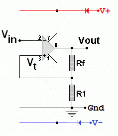
This is the simplest Schmitt trigger with positive feedback.

- Rf and R1 form a voltage divider.
- Assume that Rf = R1 to make this explanation easier to follow.
- If the Op Amp output is high (say 12 Volts).
The non inverting input will have 6 volts on it.
- The inverting input must rise above 6 Volts to make the op amp output go low.
- The Op Amp output is now low (say -12 Volts).
The non inverting input will have -6 volts on it.
- The inverting input must fall below -6 Volts to make the op amp output go high again.
- By altering Rf and R1, the threshold voltages can be adjusted to solve the problem at hand.
|
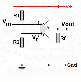
This is a comparator converted into a Schmitt trigger by adding one positive feedback resistor to give different on and off switching levels.

- If the output is low, Rf is in parallel with R2.
The combined resistance can be calculated using the resistors in parallel formula.
- If the output is high, Rf is in parallel with R1.
The combined resistance can be calculated using the resistors in parallel formula.
- The lower threshold voltage is found using the voltage divider formula with R2 in parallel with Rf.
- The upper threshold voltage is found using the voltage divider formula with R1 in parallel with Rf.
- As it's an inverting Schmitt trigger, a low input gives a high output and vice versa.
|
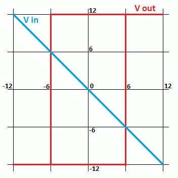
This plot shows the left Schmitt trigger behaviour.
- When the blue trace drops below -6V the red trace goes high.
- When the blue trace rises above 6V the red trace goes low.

dNoise Clean Up
As this is an inverting Schmitt Trigger, the output pulse is inverted relative to the input. Here you can see a very noisy input that would produce errors in four or five places with a simple comparator using the grey line reference voltage. The Schmitt trigger has two reference voltages. The input must go above the red line for a low output and below the blue line for a high output. This removes all noise unless the noise signal is so large that it exceeds the difference between the reference voltages. Although the amplitude noise is removed, there is still some timing noise called Jitter. The pulses might switch slightly too soon or too late. This can be removed with other digital techniques beyond A Level scope.

For the Falstad Circuit Simulation, CTRL+Click Schmitt Trigger Example
In options, check European Resistors and uncheck Conventional Current.
Adjust the slider SLOWLY and watch hysteresis in the XY oscilloscope plot.
Alternatively view Schmitt_Trigger.txt.
Save or copy the text on the web page. Import the saved or copied text into the Falstad simulator.
Here is the new HTML5 Simulator Site.
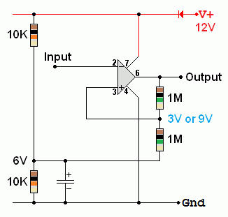
Single power rail simple Schmitt Trigger

This uses a voltage divider to produce a six volt level. The upper and lower switching levels in this exmple are 3V and 9V. The feedback resistors need to be much larger than the voltage divider resistors for this circuit to behave well.
For the Falstad Circuit Simulation, CTRL+Click Schmitt Trigger - Single Power Rail
In options, check European Resistors and uncheck Conventional Current.
Adjust the slider SLOWLY and watch hysteresis in the XY oscilloscope plot.
Alternatively view Schmitt_Trigger_Single.txt.
Save or copy the text on the web page. Import the saved or copied text into the Falstad simulator.
Here is the new HTML5 Simulator Site.
reviseOmatic V3
Contacts, ©, Cookies, Data Protection and Disclaimers
Hosted at linode.com, London


