Site Logo Home
 
rOm
Quest
Glossary
 
Random
Page
Search
Site
Lush
Sim
Class
Subject
Images
 
Help
FAQ
Sign
Up
Log
In
GCSE     Op Amp     Amplifier System     Comparator     Gain     Gain Bandwidth     >Inverting<     Non-Inverting     Power     Summing    

Op Amp Inverting


Site for Eduqas/WJEC - Go to the AQA site.

  GCSE    Op Amps  0 of 30    Question 1083    Comparator 
Score 0/0 
Not attempted  
Last Answer  
Deadline not set1 of 30    Question 1082    Comparator 
Score 0/0 
Not attempted  
Last Answer  
Deadline not set2 of 30    Question 1081    Comparator 
Score 0/0 
Not attempted  
Last Answer  
Deadline not set3 of 30    Question 1080    Comparator 
Score 0/0 
Not attempted  
Last Answer  
Deadline not set4 of 30    Question 598    Comparator 
Score 0/0 
Not attempted  
Last Answer  
Deadline not set5 of 30    Question 352    Comparator 
Score 0/0 
Not attempted  
Last Answer  
Deadline not set6 of 30    Question 350    Comparator 
Score 0/0 
Not attempted  
Last Answer  
Deadline not set7 of 30    Question 351    Comparator 
Score 0/0 
Not attempted  
Last Answer  
Deadline not set8 of 30    Question 267    Components 
Score 0/0 
Not attempted  
Last Answer  
Deadline not set9 of 30    Question 193    Gain Bandwidth Product 
Score 0/0 
Not attempted  
Last Answer  
Deadline not set10 of 30    Question 1499    Op Amp 
Score 0/0 
Not attempted  
Last Answer  
Deadline not set11 of 30    Question 1498    Op Amp 
Score 0/0 
Not attempted  
Last Answer  
Deadline not set12 of 30    Question 1497    Op Amp 
Score 0/0 
Not attempted  
Last Answer  
Deadline not set13 of 30    Question 17    Op Amp Circuits 
Score 0/0 
Not attempted  
Last Answer  
Deadline not set14 of 30    Question 18    Op Amp Circuits 
Score 0/0 
Not attempted  
Last Answer  
Deadline not set15 of 30    Question 1030    Op Amp Circuits 
Score 0/0 
Not attempted  
Last Answer  
Deadline not set16 of 30    Question 184    Op Amp Circuits 
Score 0/0 
Not attempted  
Last Answer  
Deadline not set17 of 30    Question 189    Op Amp Circuits 
Score 0/0 
Not attempted  
Last Answer  
Deadline not set18 of 30    Question 188    Op Amp Circuits 
Score 0/0 
Not attempted  
Last Answer  
Deadline not set19 of 30    Question 186    Op Amp Circuits 
Score 0/0 
Not attempted  
Last Answer  
Deadline not set20 of 30    Question 1416    Op Amp Circuits 
Score 0/0 
Not attempted  
Last Answer  
Deadline not set21 of 30    Question 597    Op Amp Circuits Ideal 
Score 0/0 
Not attempted  
Last Answer  
Deadline not set22 of 30    Question 192    Op Amp Circuits Ideal 
Score 0/0 
Not attempted  
Last Answer  
Deadline not set23 of 30    Question 348    Op Amp Circuits Ideal 
Score 0/0 
Not attempted  
Last Answer  
Deadline not set24 of 30    Question 349    Op Amp Circuits Ideal 
Score 0/0 
Not attempted  
Last Answer  
Deadline not set25 of 30    Question 1494    Op Amp Gain 
Score 0/0 
Not attempted  
Last Answer  
Deadline not set26 of 30    Question 1495    Op Amp Gain Bandwidth 
Score 0/0 
Not attempted  
Last Answer  
Deadline not set27 of 30    Question 1496    Op Amp Gain Bandwidth 
Score 0/0 
Not attempted  
Last Answer  
Deadline not set28 of 30    Question 1401    Thermistor Voltage Divider 
Score 0/0 
Not attempted  
Last Answer  
Deadline not set29 of 30    Question 1402    Thermistor Voltage Divider 
Score 0/0 
Not attempted  
Last Answer  
Deadline not set30 of 30    Question 1400    Thermistor Voltage Divider 
Score 0/0 
Not attempted  
Last Answer  
Deadline not set  Questions 0 to 30   -->  View All  

Gain   =   - Rf / R1   =   Vout / Vin        Input Impedance   =   R1        The output is 1) bigger and 2) inverted.

Inverting Amplifier in the Lushprojects Simulator
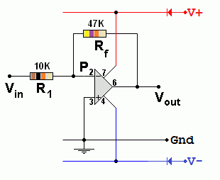
Inverting Amplifier Circuit Diagram

Feedback

Feedback is the signal from the Op Amp output, fed back to the input, through Rf. The inverting amplifier uses negative feedback to control the gain.

Oscilloscope Trace of an Inverting Amplifier

The Amplifier

  1. Increases the magnitude of the input signal.
  2. It inverts the signal. (On an oscilloscope, the waves look upside down).
  3. In the oscilloscope trace here, the output (yellow) is four times bigger than the input (red). The gain is MINUS 4.
  4. MINUS because the signal is inverted and 4 because it's four times bigger.

For Maths Experts

Ohm's Law can be used to predict the gain of the Inverting Op Amp.

No current flows into or out of ideal Op Amp inputs. Therefore the current in Rf is equal to the current in R1. Using Ohm's law (V = I R) and since the voltage at P is zero ...

Vin = -I R1          so          I = - Vin / R1

Vout = I Rf          so          I = Vout / Rf

- Vin / R1 = Vout / Rf

Gain = Vout / Vin = - Rf / R1

Measure the Gain of an Inverting Amplifier

Build this inverting amplifier and measure the gain. The volt meters should be set to the 20 Volt range.

Plot a graph showing Vin on the X axis and Vout on the Y axis. The graph gradient gives you the gain.

Gain = -Rf / R1 = - 100/10 = -10.
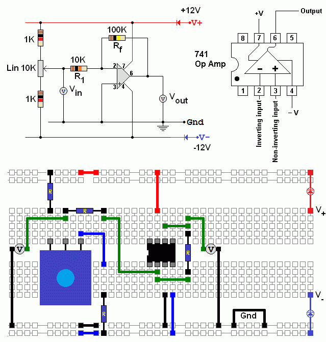
Inverting Op Amp Lab Task

Subject Name     Level     Topic Name     Question Heading     First Name Last Name Class ID     User ID    

fff
Home
<<<
ppw
Pg Up
<<
ppp
Up
<
|||

>|<
nnn
Down
>
nnw
Pg Down
>>
lll
End
>>>

Close
Escape
X

Q: qNum of last_q     Q ID: Question ID         Score: num correct/num attempts         Date Done    


Submit
Enter


Question Text

image url


Help Link

Add     Delete     Clone     Edit     Hardness

Help Text
Debug


Contact, Copyright, Cookies and Legalities: C Neil Bauers - reviseOmatic V4 - © 2016/17

Hosted at linode.com - London


Please report website problems to Neil