 Home
Home
rOm
Quest
Glossary
Random
Page
Search
Site
Lush
Sim
Class
Subject
Images
Help
FAQ
Sign
Up
Log
In
WANTED: Individual or team to take over this project. I'm in my 70's and want to put my feet up. Contact details in footer.
RC Circuit Explanation
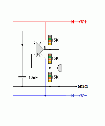
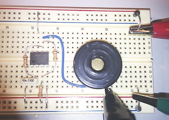
This oscillator will produce a square wave output.
This is a nice example of ...
-
A comparator
-
A voltage divider
-
A resistor capacitor timing circuit.
-
The positive feedback to the non-inverting input makes this a Schmitt Trigger circuit
-
This can also be built with a Schmitt NOT or Inverter Gate.
-
Omit all the non-inverting input components as similar circuitry is included inside the gate.
-
Assume the circuit is running on +/- 12 Volts.
-
Assume the output is high (+12 V).
-
The 15k resistors act as a potential divider so +6 volts will be fed to the + input (non-inverting).
-
The capacitor will charge towards +12 volts through the third 15k resistor.
-
When the voltage on the - input (inverting) reaches +6 volts,
the op amp will suddenly change state and the output will go low (-12 V).
-
The non-inverting input now has -6 volts on it.
-
The capacitor will charge towards -12 volts.
-
When the voltage on the - input (inverting) reaches -6 volts,
the op amp will suddenly change state and the output will go high (+12 V) and we are back to the beginning.


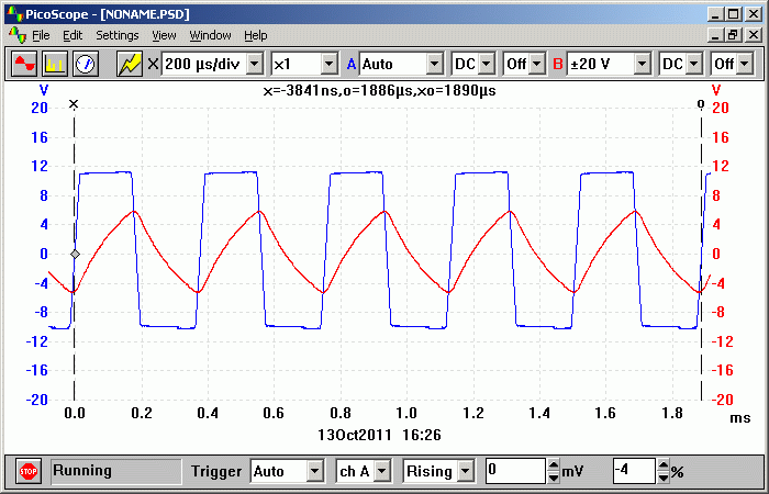
The Circuit Signals
-
The blue trace shows the operational amplifier output.
-
The red trace shows the timing capacitor filling and emptying (charging and discharging).

Schmitt Trigger or Relaxation Oscillator with a Capacitor - Falstad Simulation
Schmitt Trigger or Relaxation Oscillator with an Inductor - Falstad Simulation
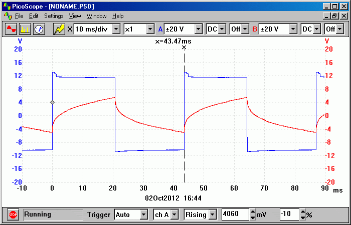
This circuit has been tried and tested. A mains transformer primary winding was used for the inductor. With the indicated resistor values, the oscillator ran at 5.5 Hz. Then the secondary winding was tested. It oscillated at about 1300 Hz due to the lower inductance. Using an Alpha-Kit solenoid, the frequency was about 11 kHz and the inverting input had quite a clean sine wave on it. This circuit ought to be useful in an Inductance Meter but the resistance of the wire inside the inductor makes it much harder to correctly calculate the inductance.
The blue trace is a good square wave output. The red trace is at the inverting input of the op amp.

Subject Name
Level
Topic Name
Question Heading
First Name
Last Name Class ID
User ID
Question Text
image url
Help Link
Add
Delete
Clone
Edit
Hardness
Help Text
Debug
- You can attempt a question as many times as you like.
- If you are logged in, your first attempt, each day, is logged.
- To improve your scores, come back on future days, log in and re-do the questions that caused you problems.
- If you are logged in, your most recent wrong answers get remembered. This might help you and your teacher to correct your understanding.
- In the grade book, you can delete your answers for a topic before re-doing the questions. Avoid deleting unless you intend re-doing the questions very soon.


