WANTED: Individual or team to take over this project. I'm in my 70's and want to put my feet up. Contact details in footer.
| AS Level Op Amp Delta Lux Gain Schmitt Astable >Schmitt Trigger< Virtual Earth Voltage Follower |
Op Amp Schmitt Trigger |
|
To fully undertand Schmitt triggers you first need to understand ...
Here is a problem that the Schmitt trigger solves. You have built a circuit to turn on some lights when it gets dark. But when the lights turn on, it gets brighter so the lights go off again. But then it is too dark so they come on again - flashing on and off rapidly.
The Schmitt trigger solves this problem by having different threshold voltages for turning on and off.
When it gets dark, the lights come on. This makes it lighter but not light enough to turn the lights off again. Later when it gets light again, the lights go off. This makes it darker but not dark enough to turn the lights on again.
This behaviour is called hysteresis. The Schmitt trigger uses positive feedback to achieve this effect.
The input signal is connected to the inverting input.
This is the simplest Schmitt trigger with positive feedback.
It has the advantage of near infinite input impedance.
The switching levels are symetrical because R1 is connected to ground.
For non symetrucal levels, connect R1 to a fixed reference voltage other that zero.
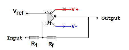
This is a comparator converted into a Schmitt trigger by adding one positive feedback resistor to give different on and off switching levels.
As this is an inverting Schmitt Trigger, the output pulse is inverted relative to the input. Here you can see a very noisy input that would produce errors in four or five places with a simple comparator using the grey line reference voltage. The Schmitt trigger has two reference voltages. The input must go above the red line for a low output and below the blue line for a high output. This removes all noise unless the noise signal is so large that it exceeds the difference between the reference voltages. Although the amplitude noise is removed, there is still some timing noise called Jitter. The pulses might switch slightly too soon or too late. This can be removed with other digital techniques beyond A Level scope.
This uses a voltage divider to produce a six volt level.
The upper and lower switching levels in this exmple are 3V and 9V.
The feedback resistors need to be much larger than the voltage divider resistors for this circuit to behave well.
Subject Name Level Topic Name Question Heading First Name Last Name Class ID User ID
|
Q: qNum of last_q Q ID: Question ID Score: num correct/num attempts Date Done
|
Question Text
image url
Help Link
Add Delete Clone Edit Hardness
Contact, Copyright, Cookies and Legalities: C Neil Bauers - reviseOmatic V4 - © 2016 to 2026
Hosted at Akamai Cloud - London
Please report website problems to Neil