Site Logo Home
 
rOm
Quest
Glossary
 
Random
Page
Search
Site
Lush
Sim
Class
Subject
Images
 
Help
FAQ
Sign
Up
Log
In
AS Level     Logic     Algebra     Bistable Latch     >Karnaugh Maps<     Multiplexing     NOR Array     Propagation Delay    

Logic Karnaugh Maps


Site for Eduqas/WJEC - Go to the AQA site.

  AS Level    Combinational Logic  0 of 26    Question 931    Gate Arrays 
Score 0/0 
Not attempted  
Last Answer  
Deadline not set1 of 26    Question 921    Gate Arrays 
Score 0/0 
Not attempted  
Last Answer  
Deadline not set2 of 26    Question 927    Gate Arrays 
Score 0/0 
Not attempted  
Last Answer  
Deadline not set3 of 26    Question 928    Gate Arrays 
Score 0/0 
Not attempted  
Last Answer  
Deadline not set4 of 26    Question 929    Gate Arrays 
Score 0/0 
Not attempted  
Last Answer  
Deadline not set5 of 26    Question 930    Gate Arrays 
Score 0/0 
Not attempted  
Last Answer  
Deadline not set6 of 26    Question 943    Karnaugh Maps 
Score 0/0 
Not attempted  
Last Answer  
Deadline not set7 of 26    Question 942    Karnaugh Maps 
Score 0/0 
Not attempted  
Last Answer  
Deadline not set8 of 26    Question 941    Karnaugh Maps 
Score 0/0 
Not attempted  
Last Answer  
Deadline not set9 of 26    Question 940    Karnaugh Maps 
Score 0/0 
Not attempted  
Last Answer  
Deadline not set10 of 26    Question 939    Karnaugh Maps 
Score 0/0 
Not attempted  
Last Answer  
Deadline not set11 of 26    Question 938    Karnaugh Maps 
Score 0/0 
Not attempted  
Last Answer  
Deadline not set12 of 26    Question 937    Karnaugh Maps 
Score 0/0 
Not attempted  
Last Answer  
Deadline not set13 of 26    Question 936    Karnaugh Maps 
Score 0/0 
Not attempted  
Last Answer  
Deadline not set14 of 26    Question 935    Karnaugh Maps 
Score 0/0 
Not attempted  
Last Answer  
Deadline not set15 of 26    Question 934    Karnaugh Maps 
Score 0/0 
Not attempted  
Last Answer  
Deadline not set16 of 26    Question 146    Logic Gate Rules 
Score 0/0 
Not attempted  
Last Answer  
Deadline not set17 of 26    Question 125    Logic Gate Rules 
Score 0/0 
Not attempted  
Last Answer  
Deadline not set18 of 26    Question 124    Logic Gate Rules 
Score 0/0 
Not attempted  
Last Answer  
Deadline not set19 of 26    Question 123    Logic Gate Rules 
Score 0/0 
Not attempted  
Last Answer  
Deadline not set20 of 26    Question 122    Logic Gate Rules 
Score 0/0 
Not attempted  
Last Answer  
Deadline not set21 of 26    Question 577    Truth Tables 
Score 0/0 
Not attempted  
Last Answer  
Deadline not set22 of 26    Question 576    Truth Tables 
Score 0/0 
Not attempted  
Last Answer  
Deadline not set23 of 26    Question 573    Truth Tables 
Score 0/0 
Not attempted  
Last Answer  
Deadline not set24 of 26    Question 128    Truth Tables 
Score 0/0 
Not attempted  
Last Answer  
Deadline not set25 of 26    Question 127    Truth Tables 
Score 0/0 
Not attempted  
Last Answer  
Deadline not set26 of 26    Question 126    Truth Tables 
Score 0/0 
Not attempted  
Last Answer  
Deadline not set  Questions 0 to 26   -->  View All  

Counter Control System

A common type of control system uses a binary counter which counts from 0 to 15. When the counter reaches a particular number, the control system performs a suitable action. These control systems produce long, complicated Boolean expressions and complex circuits. Often the circuits can be simplified a lot.

The circuit below is designed to operate a machine whenever the counter reaches 2, 4, 5 or 6.

Gate-Karnough-1.gif

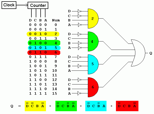
In this circuit, the AND gates are wired up to DECODE or respond to particular numbers. They are colour coded and labelled to show which number. The rows in the table have matching colour codes. The Boolean expression is also colour coded to show which part of the expression matches each number or row in the table.

In plain English, the circuit detects 2, 4, 5 or 6.

Simplifying the Circuit

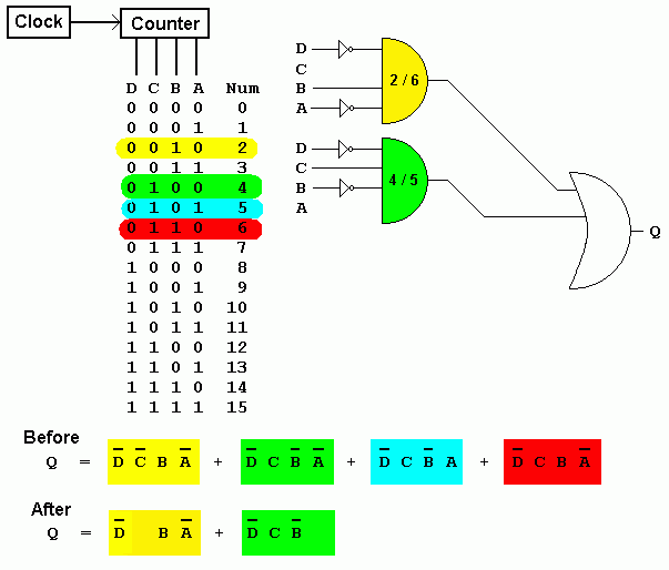
In the Karnaugh map, ONEs are positioned in the squares that match the binary row numbers in the table. These have been colour coded to show which is which. Whenever ONEs group horizontally or vertically, for example in pairs or fours, it is possible to simplify the logic of the circuit.

  B A B A B A B A
D C 0 0 0 1 1 1 1 0
0 0       1
0 1 1 1   1
1 1        
1 0        

Looking at the Green (4) and Blue (5) squares, you can deduce that the value of A has no effect on that pair of squares. This means that the FOUR and FIVE detectors can be replaced with a single circuit and input A does not need to be wired up.

Similarly looking at the Yellow (2) and Red (6) squares, you can deduce that the value of C has no effect on that pair of squares. This means that the TWO and SIX detectors can be replaced with a single circuit and input C does not need to be wired up.

The Simplified Solution

Gate-Karnough-2.gif

Subject Name     Level     Topic Name     Question Heading     First Name Last Name Class ID     User ID    

fff
Home
<<<
ppw
Pg Up
<<
ppp
Up
<
|||

>|<
nnn
Down
>
nnw
Pg Down
>>
lll
End
>>>

Close
Escape
X

Q: qNum of last_q     Q ID: Question ID         Score: num correct/num attempts         Date Done    


Submit
Enter


Question Text

image url


Help Link

Add     Delete     Clone     Edit     Hardness

Help Text
Debug


Contact, Copyright, Cookies and Legalities: C Neil Bauers - reviseOmatic V4 - © 2016/17

Hosted at linode.com - London


Please report website problems to Neil