 Home
Home
rOm
Quest
Glossary
Random
Page
Search
Site
Lush
Sim
Class
Subject
Images
Help
FAQ
Sign
Up
Log
In
WANTED: Individual or team to take over this project. I'm in my 70's and want to put my feet up. Contact details in footer.
Normal or Stepper?
Big, high speed motors need to have a conventional design. Trying to move a really large motor in steps might rip it off its mountings.
Small precision motors with robotic accuracy need to have the stepper design. Accurate position control becomes possible.
-
Stepper motors rotate through precise angular steps giving perfect position control.
-
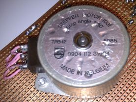
Stepper motors are manufactured with steps per revolution of 12, 24, 48, 72, 144, 180, and 200.
-
These give shaft rotation angles of 30, 15, 7.5, 5, 2.5, 2, and 1.8 degrees per step.
-
Stepper motors come in bipolar and unipolar versions with both 4 pole or 6 pole devices.
 7.5o steps 3.75o steps
For more precise control, a stepper motor is needed. These are used when accurate position control is needed. Examples include robotic movement control, printer head movement control and disk drive head positioning.
-
They step through a small known angle so it is possible to know the exact angular position of the motor.
-
They are usually small.
-
They are used for precise movement control in robotics and also in computer printers and disk drives.
-
Ideal for controlling small precise movements in either direction.
-
Hard and expensive to make very large stepper motors although kilowatt powers are available.
-
More complex electronics is needed to control the motor, involving programming, data tables and a PIC chip or microcontroller.
-
Accurate control is possible without negative feedback and a closed loop although this is sometimes included for additional safety and reliability.
-
Difficult to control at high speeds.
-
Poor efficiency converting electrical energy to mechanical.
-
The rotation angle of the motor depends only on the input pulses.
-
The motor has full torque at standstill if the electromagnets are turned on.
-
Precise repeatable positioning is possible without positional drift.
-
Excellent start/stop/reverse response.
-
Reliable because there are no sliding contact brushes in the motor.
-
Easy to build open-loop motor control systems.
-
Excellent low speed performance especially with a gear box.
Unipolar Stepper Motor - Five or Six Connections
Connection 1 and 2 are sometimes joined together inside the motor.
Driver Circuit
-
Unipolar motors have centre tapped coil windings.
-
Only half the coil is energised at any time.
-
If current flows from A to 1, the magnetic field will be established.
-
If the current flows from B to 1, the field will be reversed.
-
Likewise for coil 2.
-
Four simple MOSFET switching circuits can be used to drive these coils.
-
Bipolar transistors could be used instead.
Bipolar Stepper Motors - Four Connections
To reverse the magnetic field in the coils, an H-Bridge circuit is used. This is more complex than the unipolar arrangement above.
This circuit is able to energise the stepper motor coils in either direction. Two H-Bridge circuits are used, one for each coil.
Stepper Motor Drivers
-
Four coil stepper motors can be controlled with four MOSFET switch circuits.
-
Bipolar motors need the current to be reversed so H-Bridge controllers are ideal.
A Possible Physical Layout
Here is an approximation of one possible physical layout for a stepper motor. Only two of the eight coils are shown.
Subject Name
Level
Topic Name
Question Heading
First Name
Last Name Class ID
User ID
Question Text
image url
Help Link
Add
Delete
Clone
Edit
Hardness
Help Text
Debug
- You can attempt a question as many times as you like.
- If you are logged in, your first attempt, each day, is logged.
- To improve your scores, come back on future days, log in and re-do the questions that caused you problems.
- If you are logged in, your most recent wrong answers get remembered. This might help you and your teacher to correct your understanding.
- In the grade book, you can delete your answers for a topic before re-doing the questions. Avoid deleting unless you intend re-doing the questions very soon.