WANTED: Individual or team to take over this project. I'm in my 70's and want to put my feet up. Contact details in footer.
| AS Level Sequential Logic >Synchronous Counter< Up Counter and Reset |
Sequential Logic Synchronous Counter |
|
Once you understand this topic you'll realise why microcontrollers were invented. "WTF!. I'll just use a microcontroller and a look-up table."
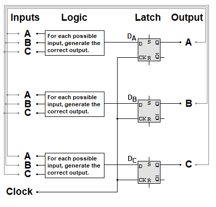
On the rising edge of the clock pulse, each input DA, DB or DC is copied to QA, QB or QC.
The combinational logic computes the next counter state from the inputs A, B and C (which are the outputs from the latch).
A: Fill
B: Wash
C: Drain
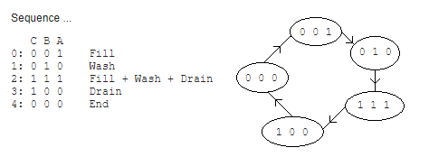
Sequence ...
C B A
0: 0 0 1 Fill
1: 0 1 0 Wash
2: 1 1 1 Fill + Wash + Drain (amounts to rinse).
3: 1 0 0 Drain
4: 0 0 0 End
Sequence diagrams are used where the data from the table above are put in a pretty diagram showing just the latch outputs at each stage.
Here is the diagram showing the unused states leading back to the 0,0,0 state. They could lead back to any point on the diagram if that proved useful.
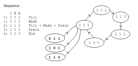
A truth table describing all the states and next-states (the next states are the same as the current states, shifted up one place in the table). The unused states often point to the "stop" or "start" or "end" state. If it does not matter what happens after an unused state, these can be made to point to any step in the table to save circuitry (and cost).
| Sequence | Current Output | Next Output after Clock Pulse | ||||
| Step | C | B | A | Dc | Db | Da |
| 0 | 0 | 0 | 1 | 0 | 1 | 0 |
| 1 | 0 | 1 | 0 | 1 | 1 | 1 |
| 2 | 1 | 1 | 1 | 1 | 0 | 0 |
| 3 | 1 | 0 | 0 | 0 | 0 | 0 |
| 4 | 0 | 0 | 0 | 0 | 0 | 1 |
| Unused States | ||||||
| 5 | 0 | 1 | 1 | 0 | 0 | 0 |
| 6 | 1 | 0 | 1 | 0 | 0 | 0 |
| 7 | 1 | 1 | 0 | 0 | 0 | 0 |
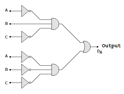
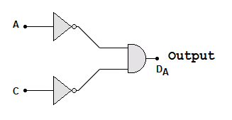
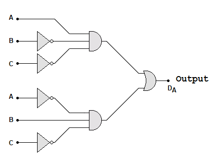
Da is high if the input C,B,A is 010 or 000 - this circuit detects these and only these conditions
But it might be possible to simplify this circuit using a Karnaugh Map where pairs (or fours) of ones can be grouped. The yellow highlight shows a pair. This shows that C must be zero and it does not matter what value B has. So B does not need to be wired up! Some people with good pattern recognition can stare at the truth table and spot this pattern and get it right without Karnaugh maps. For others, it's safer to do "colouring in" to spot the patterns!
| B A | B A | B A | B A | |
| C | 0 0 | 0 1 | 1 1 | 1 0 |
| 0 | 1 | 0 | 0 | 1 |
| 1 | 0 | 0 | 0 | 0 |
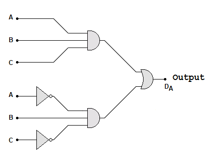
Here is the new simplified circuit ...
Db is high if the current state is 001 or 010.
| B A | B A | B A | B A | |
| C | 0 0 | 0 1 | 1 1 | 1 0 |
| 0 | 0 | 1 | 0 | 1 |
| 1 | 0 | 0 | 0 | 0 |
There are no pairs or fours so this can't be simplified.
Dc is high if C,B,A is 010 or 111
| B A | B A | B A | B A | |
| C | 0 0 | 0 1 | 1 1 | 1 0 |
| 0 | 0 | 0 | 0 | 1 |
| 1 | 0 | 0 | 1 | 0 |
There are no pairs or fours so this can't be simplified.
If you were going to build a single washing machine, it would be cheaper to build this controller from D Type Flip Flops and other simple logic gates. If your industry was planning a run of a million wahsing machines, you'd be better off using a programmable logic array. This consists of many NAND (or NOR) gates that can be interconnected by programming the chip. This allows a single low cost PLA to be used instead of a bunch of separate chips. You might only save 50p per controller but that's half a million quid saved!
Subject Name Level Topic Name Question Heading First Name Last Name Class ID User ID
|
Q: qNum of last_q Q ID: Question ID Score: num correct/num attempts Date Done
|
Question Text
image url
Help Link
Add Delete Clone Edit Hardness
Contact, Copyright, Cookies and Legalities: C Neil Bauers - reviseOmatic V4 - © 2016 to 2026
Hosted at Akamai Cloud - London
Please report website problems to Neil