WANTED: Individual or team to take over this project. I'm in my 70's and want to put my feet up. Contact details in footer.
| A Level Modulation >AM< Digital FM PAM PCM PPM PWM |
Modulation AM |
|
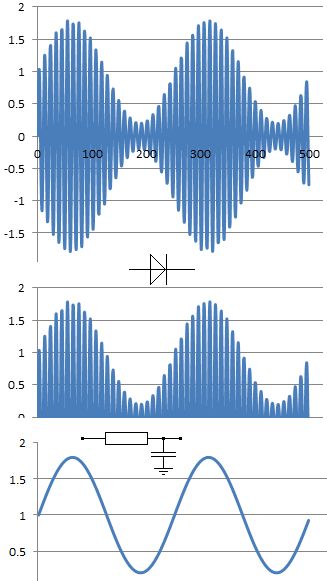
AM transmitters vary the amplitude of the carrier wave.
Example: A microphone converts sound waves (energy) into an electrical signal (energy) proportional to the sound wave pressure. These frequencies are too low to transmit. A high frequency carrier wave is needed. This can be transmitted. The carrier wave is modulated (varied) by the signal from the microphone.
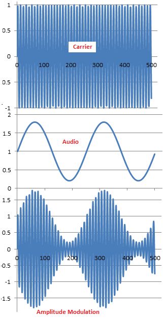
This diagram shows about 80% modulation. The carrier amplitude rises to 180% and drops to 20%. The percentage modulation depth can rise to 100% without problems.
If the modulation depth rises above 100%, the transmission looks like this.
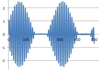
The carrier has completely gone for part of the audio cycle. This results in severe distortion. The transmission also splatters outside its usual bandwidth causing interference to stations on adjacent channels. This situation must be avoided.
When music and speech are transmitted, many frequencies are modulated onto the carrier and the sidebands look more like this (diagram below), varying rapidly as the content of the broadcast changes. The image below shows the spectrum of an AM transmission with a carrier on 700kHz and audio signals with frequencies ranging between 300 and 4000 Hz. AQA have set exam questions where you need to sketch this diagram with all the labels and frequencies correctly positioned.
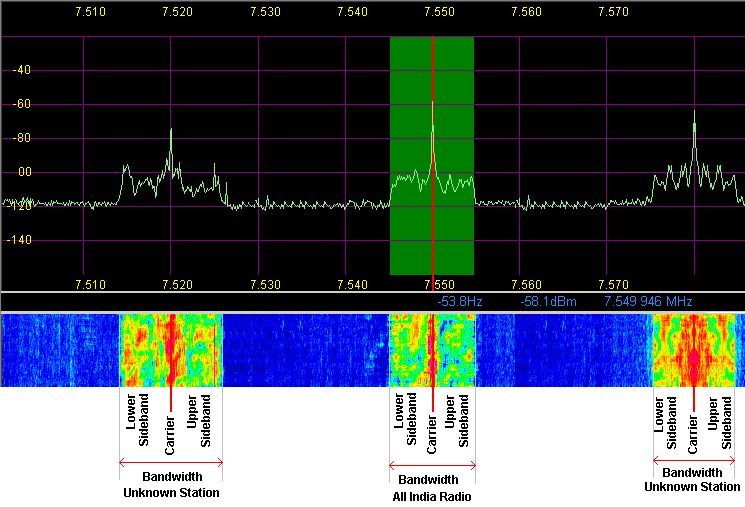
Here is a screen shot showing the spectrum of three shortwave AM broadcasting stations. The three carriers can easily be seen. The bandwidth is also clearly visible. The sidebands for each station look different because they are changing rapidly depending on the speech or music being transmitted. The green rectangle shows the band pass filtering used in the receiver so only one station comes out of the loudspeaker. Digital signal processing allows the spectrum on each side of the selected station to be seen. This advanced receiver can be re-tuned with a single mouse click but it also relies on the attached computer to do a lot of signal processing work. The colourful area below the spectrum plot shows how much energy is present at each frequency over a period of time. Blue is the background noise (sometimes called static). Yellow is a strong signal and red is a very strong signal.
Bandwidth = 2 x fmax
All the information in an AM transmission is in the sidebands. The carrier could be removed and the transmission would still work. This is called Double Sideband (suppressed carrier). Removing the carrier makes the transmitter more efficient but the bandwidth is not reduced.
By using high performance filters, it is possible to remove the carrier and also one sideband. This leaves a Single Sideband (SSB). These transmissions occupy less than half the bandwidth or spectrum space of an AM transmission. This is useful because the transmitter is more efficient and more transmissions can be crammed into the limited spectrum space available. To demodulate DSB or SSB, the carrier must be artificially replaced on the exact correct frequency. This makes DSB and SSB transmissions tricky to tune in. A mistuned receiver makes the person sound like Donald Duck. SSB is not used for commercial broadcasting because it is too hard to tune in (especially for music). It's efficiency and narrower bandwidth make it ideal for military, shipping, air traffic, industrial and amateur radio voice communication.
Note the missing carrier and only one sideband.
Subject Name Level Topic Name Question Heading First Name Last Name Class ID User ID
|
Q: qNum of last_q Q ID: Question ID Score: num correct/num attempts Date Done
|
Question Text
image url
Help Link
Add Delete Clone Edit Hardness
Contact, Copyright, Cookies and Legalities: C Neil Bauers - reviseOmatic V4 - © 2016 to 2026
Hosted at Akamai Cloud - London
Please report website problems to Neil