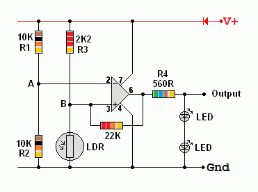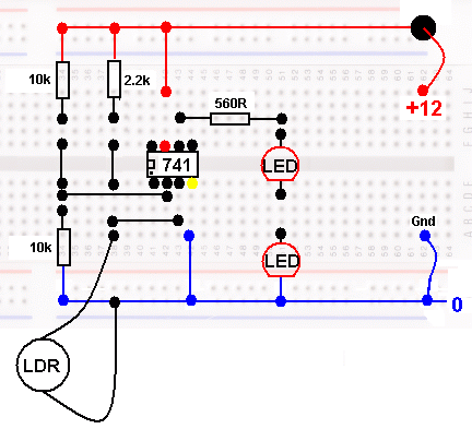
Build the circuit without the 22K positive feedback resistor.
R1 and R2 form a voltage divider.
The potential at A will be about 6 Volts.
R1 and R2 could be replaced with a potentiometer.
This would make the switch over light level level adjustable.
R3 and the LDR form another potential divider.
The potential at B depends on the light level. As it get darker, the potential increases.
When the potential at B is greater than the potential at A, the 741 operational amplifier output goes high and the LEDs come on.
R4 limits the current through the LED to less than 20mA.
Two LEDs are needed because, when the Op Amp pin 6 voltage is low, there may still be as much as two volts present.
This could be enough to light a single LED. With two LEDs, four volts are needed.
The Op Amp pin 6 voltage will be well below 4V so the LEDs will be off.
Adding the 22K resistor adds some positive feedback and the on and off threshold voltages will now differ slightly. Adding this resistor converts the circuit from a Comparator to a Schmitt Trigger.

Tasks
Set the supply voltage to +12 Volts as accurately as you can.
When the LEDs are on, measure the Op Amp output potential on pin 6.
When the LEDs are off, measure the Op Amp output potential on pin 6.
Measure the current through the LEDs. It should be about 10mA.
Problem Circuit
If you shade the LDR just right, you can make the LEDs come half on.
In real life, this could be a problem. For example street lights should not come half on.
When you add the 22K resistor, the problem is solved.
The ON and OFF light levels are now different and the "half on" problem goes away.
With 22k, the effect is not very noticeable.
Try 1.8k for very noticeably different ON and OFF light levels.
This new circuit is called a Schmitt Trigger.
The 22K resistor provides positive feedback by feeding part of the output back to the non inverting input.
