
RANDOM PAGE
SITE SEARCH
LOG
IN
SIGN UP
HELP
To gain access to revision questions, please sign up and log in.
Everyone
Data Sheet
aKey Facts
This is an oscillator circuit providing a square wave output.
The astable has zero stable states. Whichever state it is in (high or low), it will soon switch to the other state.
The 555 chip CAN NOT drive a normal 8 Ohm loudspeaker. Piezoelectric sounders can be plugged straight in.
- A DC blocking capacitor may be needed with a resistor in series to limit the output current to less that 200 mA. 27 Ohms should be suitable for a 12 Volt circuit.
- The DC Blocking capacitor (if used) should have a low reactance at the operating frequency.
- The astable frequency depends on C1.
- The circuit below uses a piezoelectric sounder and a coupling capacitor is not needed.
- The output LED indicator is optional.
bHow it Works - Exam Answer
- If the output is high, the discharge transistor is off.
- C1 charges towards Vs through Ra and Rb until the threshold rises above 2/3 of the supply voltage.
- The output goes low and the discharge transistor turns on.
- C1 discharges towards 0 Volts through Rb until the threshold drops below 1/3 of the supply voltage.
- The output goes high again and the steps above repeat.
cFrequency
The astable will oscillate at this frequency ...
F = 1.44 / ((Ra + 2Rb) C1)
dLow Time
The square wave output is low for the following period ...
tL = 0.7 RbC1
eHigh Time
The square wave output is high for the following period ...
tH = 0.7 (Ra + Rb) C1
fSymmetrical Square Wave
- To get a fairly symmetrical square wave, Ra should be a lot smaller then Rb.
- For adjustable frequencies, Rb can be a variable resistor.
- Try using an LDR for Rb. The frequency will depend on the light level.
gMark Space Ratio
- The mark space ratio is a measure of the proportion of the time the output is high.
- For example if the output was high 80% of the time and low for 20% of the time, the mark space ratio would be 4 or 4:1
- Mark Space Ratio = tH / tL
hThings to Try
Use a potentiometer to adjust the frequency.
Replace the Rb timing resistor with a light dependent resistor (LDR).
iFalstad Simulation
For the Falstad Circuit Simulation, CTRL+Click 555 Astable
In options, check European Resistors and uncheck Conventional Current.
Alternatively view 555astable.txt.
Save or copy the text on the web page. Import the saved or copied text into the Falstad simulator.
Here is the new HTML5 Simulator Site.
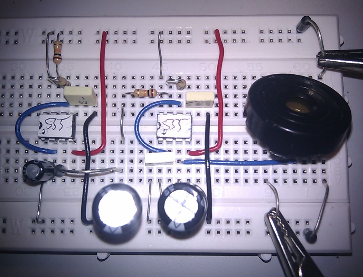
jBeep Beep Alarm Sound
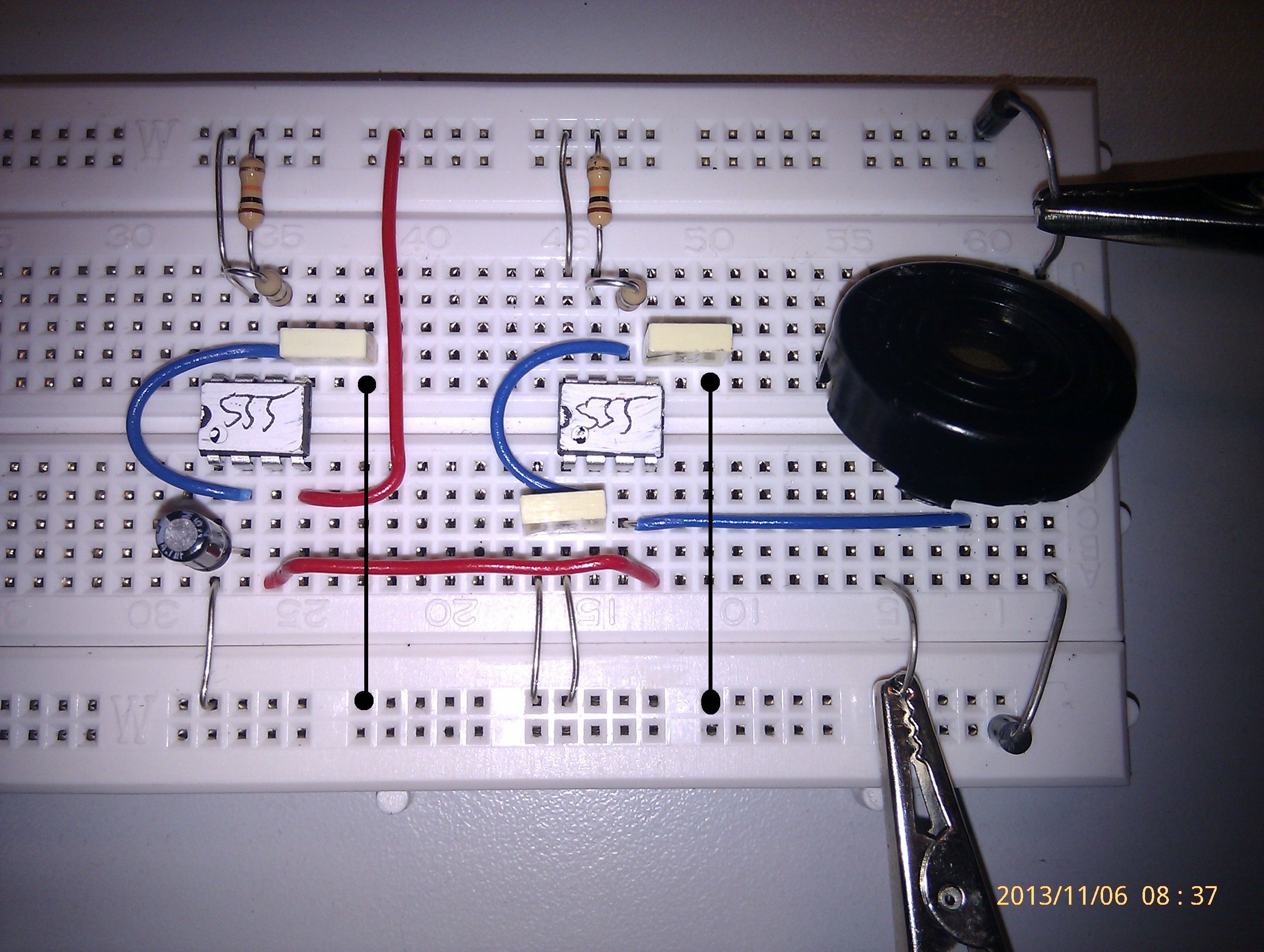
kWailing Alarm Sound
reviseOmatic V3
Contacts, ©, Cookies, Data Protection and Disclaimers
Hosted at linode.com, London