RANDOM PAGE
SITE SEARCH
LOG
IN
SIGN UP
HELP
To gain access to revision questions, please sign up and log in.
Everyone
Data Sheet
Key Facts
- When triggered, the monostable produces a single accurately timed pulse. The output goes high for the timed period and then goes low again.
- The monostable has one stable state and one unstable state.
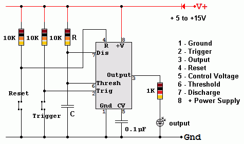
- In the circuit below, the 10k pull-up resistor pulls pin 2 high.
- Pressing the switch sends a LOW trigger pulse to pin 2.
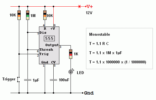
- This turns on the output for a time T = 1.1 R C
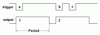
- The duration of the output pulse is called its period.
- The reset switch can be pressed to end the timing earlier than normal.
How it Works - Exam Answer
- The timer starts when the trigger voltage drops below Vs / 3.
- The output goes high and the discharge transistor turns off. Trigger pulses are ignored.
- C charges through R towards Vs.
- When the voltage across C reaches 2/3 of Vs, the timer resets. This takes 1.1 R C Seconds.
- The output goes low.
- The discharge transistor turns on and quickly discharges C to zero volts.

Pulse Time
The square wave output is high for the following period ...
T = 1.1 R C
Timing Diagram

- The trigger pulse (a) turns on the output for a fixed time.
- Trigger pulse (b) turns the output on again.
- Trigger pulse (c) is IGNORED because the output is already on.
Something to Build
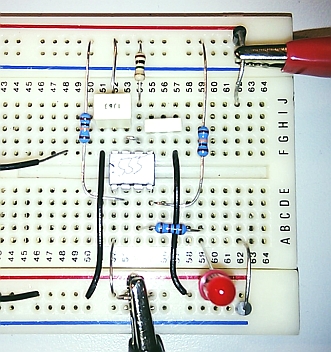
This produces a 1.1 second pulse when triggered. The LED should come on for 1.1 seconds. The black wire on the left is an improvised switch.


Falstad Simulation
For the Falstad Circuit Simulation, CTRL+Click 555 Monostable
In options, check European Resistors and uncheck Conventional Current.
Click the logic input low and high again to trigger the monostable.
Alternatively view 555_Monostable.txt.
Save or copy the text on the web page. Import the saved or copied text into the Falstad simulator.
Here is the new HTML5 Simulator Site.
reviseOmatic V3
Contacts, ©, Cookies, Data Protection and Disclaimers
Hosted at linode.com, London


