RANDOM PAGE
SITE SEARCH
LOG
IN
SIGN UP
HELP
To gain access to revision questions, please sign up and log in.
Everyone
Data Sheet
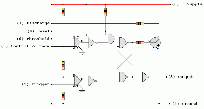
There are several versions of this diagram. This one uses subsystems included in the AQA exam specification. The internal modules include ...
- The three 5k resistors used as voltage dividers
- Two Op' Amp' Comparators
- The RS Flip Flop / Bistable Latch
- The Output Buffer / Driver
- NPN Transistor used as a switch.

For the Falstad Circuit Simulation, CTRL+Click 555 Astable Based on the Circuit Above
In options, check European Resistors and uncheck Conventional Current.
Alternatively view 555_Insides.txt.
Save or copy the text on the web page. Import the saved or copied text into the Falstad simulator.
Here is the new HTML5 Simulator Site.
Inside the 555 timer you will find ...
- Voltage Divider consisting of three 5kΩ resistors.
- These three 5k resistors may explain the name of this device.
- The threshold comparator goes high if the threshold input goes above 2/3 of the supply voltage.
- The trigger comparator goes high if the trigger input voltage drops below 1/3 of the supply voltage.
- Threshold Comparator. If the threshold input is greater than 2/3 Vs, the latch resets and the output goes low. The discharge transistor turns on and this pulls pin 7 (discharge) low too.
- Trigger comparator. If the trigger input is less than 1/3 Vs, the latch is set and the output goes high. The discharge transistor turns off and pin 7 (discharge) is controlled by components external to the 555 chip.
- Data Latch. This RS Flip Flop is set if the trigger input is less than 1/3 Vs. It is reset if the threshold input is greater than 2/3 Vs.
- Output Buffer. This is able to source or sink up to 200mA to the output.
- Reset (pin 4). If pin 4 is low, this resets or disables the timer and the other inputs have no effect.
- Discharge. This pin is held low by an NPN transistor used as a switch. This happens when the 555 output is low. If the 555 output is high, this transistor turns off and it has no effect on the rest of the circuit. (This arrangement is called "open collector").
This diagram is worth understanding because each subsystem might be included in the exam.
reviseOmatic V3
Contacts, ©, Cookies, Data Protection and Disclaimers
Hosted at linode.com, London


