
Bipolar Junction Transistor |
|
To gain access to revision questions, please sign up and log in.

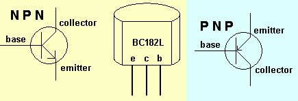
A small current flowing in the base controls a much larger current flowing through the emitter to collector. (Don't confuse these current controlled devices with MOSFETs which are voltage controlled.)
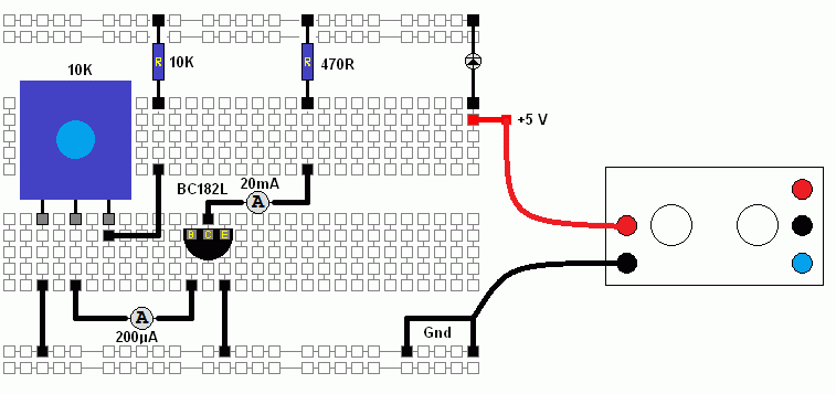
The circuit below can be used to measure base and collector currents.
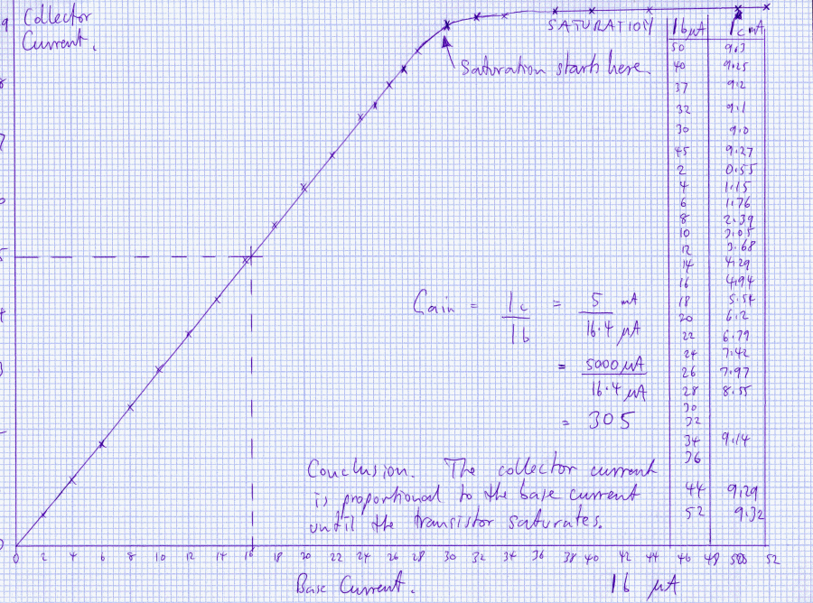
Current Gain = Ic / Ib
This value depends on the model of transistor and can be anything between about 10 and 400.
Because a small current is controlling a much larger current, transistors can be used as amplifiers and switches.
About 0.7 volts is needed before a current starts to flow in the base of the transistor.
Under normal conditions the collector current is proportional to the base current.
When the base voltage is too small and no current is flowing in the collector, the collector voltage is equal to the supply voltage. The transistor is said to be "cut off".
When the transistor is saturated (Ic is limited only by R2) the collector voltage is about 0.2V.
Build this circuit and plot a graph showing how the collector and base currents are related.
You may find it difficult to take the measurements because the readings tend to creep up or down depending on the temperature of the transistor.


reviseOmatic V3 Contacts, ©, Cookies, Data Protection and Disclaimers Hosted at linode.com, London