RANDOM PAGE
SITE SEARCH
LOG
IN
SIGN UP
HELP
To gain access to revision questions, please sign up and log in.
AS
A2
Source Follower Properties

- The voltage gain is One.
- Current gain is large.
- Power gain is large.
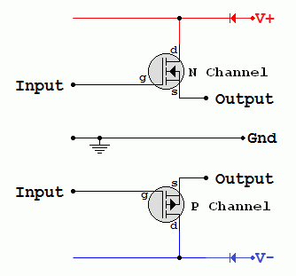
- s = SOURCE.
- g = GATE.
- d = DRAIN.
- Extremely high input or gate resistance (Close to infinity).
- The N Channel device amplifies positive signals.
- The P Channel device amplifies negative signals.
- Ideal device: Vout = Vin.
- A 2 to 4 volt drop depending on the MOSFET.
- Real life device: Typical N Channel: Vout = Vin - 2.
- Real life device: Typical P Channel: Vout = Vin + 2.
MOSFET Characteristics

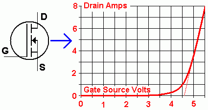
This graph is for a power MOSFET such as the IRF520 device. You can see that the device does not start conducting until the gate voltage is significantly greater than 3 Volts. An ideal MOSFET would give a straight line graph starting from zero. This graph also explains the 2 to 4 Volt drop mentioned above.
Source Follower Power Calculations

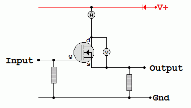
DC Power is calculated using Volts x Amps. This is the current through the MOSFET and the voltage across the MOSFET.
There are three commonly occurring states.
- The MOSFET is turned off. The current is zero and the power dissipated = zero.
- The MOSFET is saturated.
- An ideal MOSFET would have zero volts across it.
- Under these conditions the power dissipated is zero again.
- A real MOSFET might have 20 mV across it. (This will be in the data sheet or specified in the exam question).
- In this case, do the Volts x Amps calculation and expect a small answer.
- The third state is where the MOSFET is conducting and not saturated.
- This will result in the highest heat dissipation.
- Work out Volts x Amps.
- A heatsink will often be needed in higher power circuits.
AC Power Calculations
- Use the RMS values for the voltage across the MOSFET and the current through the it.
- RMS Value = 0.7 x Peak Value
Source Follower Experiment

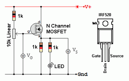
- Build this circuit and measure VG and VS.
- Plot a graph showing how these are related.
- Run the circuit on 12 Volts.
reviseOmatic V3
Contacts, ©, Cookies, Data Protection and Disclaimers
Hosted at linode.com, London


