Dimmable LED |
|
To gain access to revision questions, please sign up and log in.
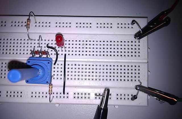
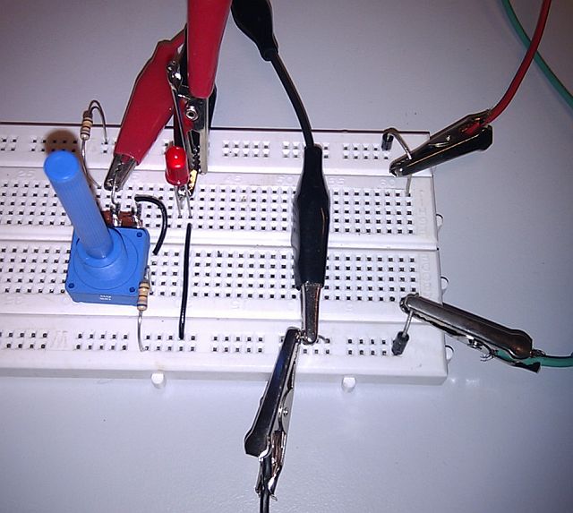
Build the Circuit and Adjust the Potentiometer
|
|
|
|
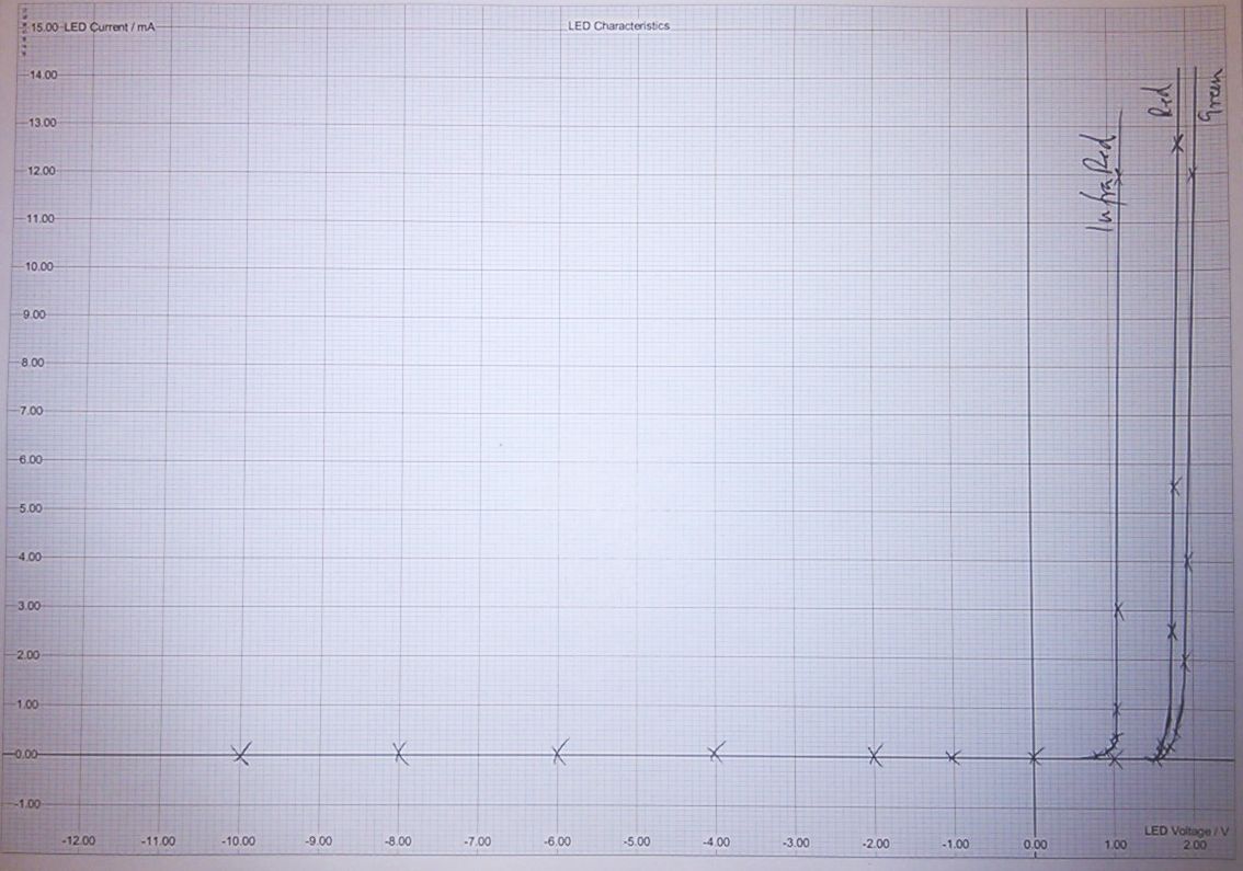
The LED is at risk with negative or reverse bias voltages. If the voltage is too great, the LED could be destroyed.
Note that there are few measurements in the straight non-interesting parts of the graphs and lots of measurements where the graphs turn the corner. This is good scientific technique.
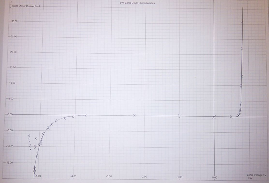
The same test circuit can be used but drop the 680Ω resistors down to 330Ω to increase the currents a little.
This graph shows the Zener voltage becoming significantly inaccurate below 10mA.
reviseOmatic V3 Contacts, ©, Cookies, Data Protection and Disclaimers Hosted at linode.com, London