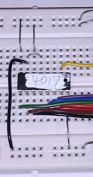
4017 Mini Project |
|
To gain access to revision questions, please sign up and log in.
The circuit will ... |
Reasons |
Testing |
|
1) |
Run on 4.5 to 6 Volts |
|
Use a multimeter to test at the lowest, highest and intermediate voltages. |
2) |
Have a 4 to 5Hz clock. |
To flash the LEDs quickly but not so fast that they blur. |
Use a Picoscope to measure the clock period. Calculate the frequency. |
3) |
Consume less than 20 mA. |
Using 2500 mAh cells, the battery life will be better than 125 Hours. |
Use a multimeter measure the current at the highest voltage setting. |

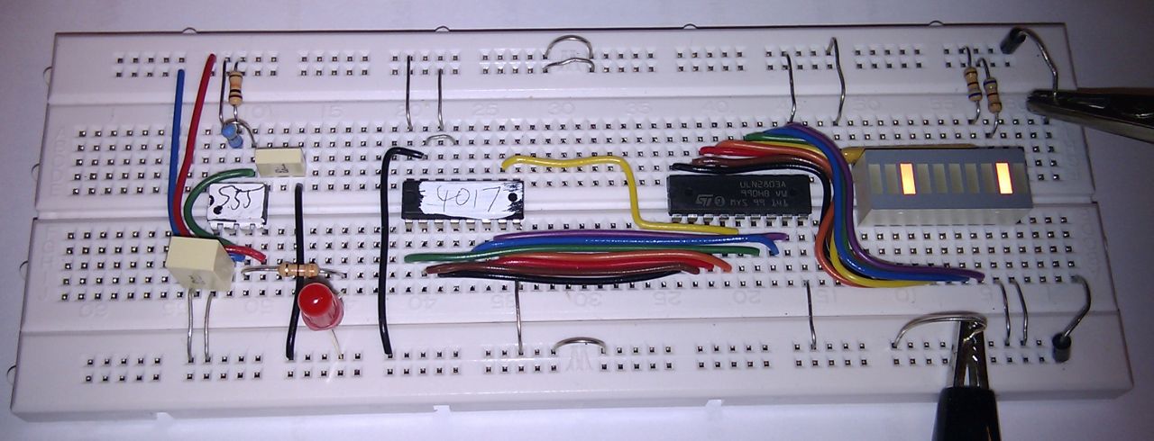
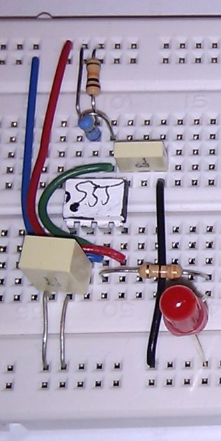
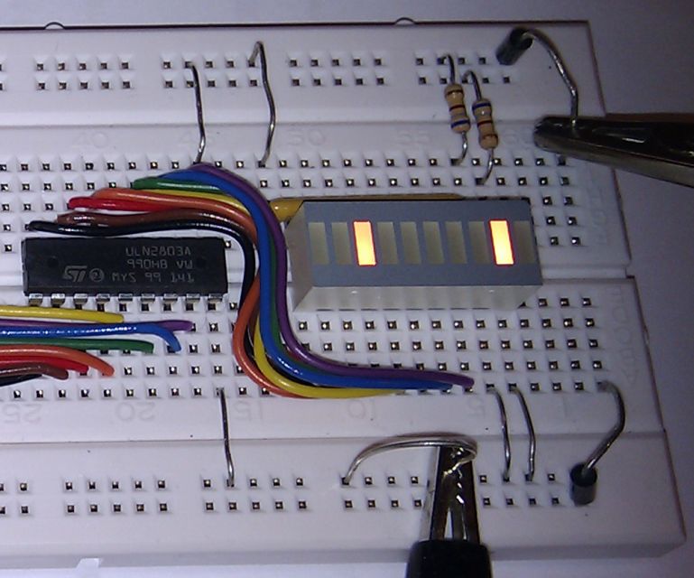
Note the colour coded wiring!
reviseOmatic V3 Contacts, ©, Cookies, Data Protection and Disclaimers Hosted at linode.com, London