RANDOM PAGE
SITE SEARCH
LOG
IN
SIGN UP
HELP
To gain access to revision questions, please sign up and log in.
AS
A2
Power Generation
Photodiodes produce a voltage when light shines on them. This is how solar cells work. Solar cells are arrays of large numbers of photodiodes. They have a large surface area and coatings to maximise light absorption. This is the best arrangement for generating power.
Light Detection
If a reverse leakage current is flowing in the photodiode, this current is greatly increased by incident light. This is the best arrangement for detecting light.
Simple Detector
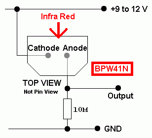
A typical photodiode is the BPW41N. Here is a diagram showing the pinout and typical component values. Note that the diode is reverse biased and its operation relies on leakage current caused by incident light.
The current through the diode is about 0.5 µA in the dark rising to 100 µA when brightly lit by infra red light.
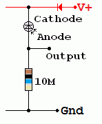
Here is a layout and circuit diagram showing typical component values for the BPW41N detector.
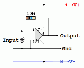
On the right is an Op Amp, current to voltage converter. It converts the diode leakage current into a voltage.


Op Amp Detector / Receiver for Infra Red Amplitude Modulation

- R1 and R2 form a voltage divider. This allows the 741 Op Amp to be used without a negative supply.
- C1 is a decoupling capacitor. This ensures the voltage divider output is steady with no AC signals present.
- The photodiode passes almost no current in the dark.
When lit, a leakage current flows.
- The 741 inverting input is a virtual earth.
When the diode leakage current flows, the output voltage alters to maintain the virtual earth.
Vout = Leakage Current x R3.
If R3 is made bigger, the circuit becomes more sensitive but there is also more noise (a hissing sound).
- C2 is a coupling capacitor.
AC signals from the 741 chip are passed to the LM386 Audio Amplifier.
DC signals are blocked.
- The Potentiometer is used as a volume control coltage divider.
- C4 is a coupling capacitor.
It couples the audio output to the loudspeaker while blocking the DC voltage.
- C3 and R4 make an equalisation circuit.
This is needed to prevent high frequency oscillations in the LM386 amplifier.
- C5 is a power supply decoupling capacitor.
It prevents low frequency oscillations in this circuit.
reviseOmatic V3
Contacts, ©, Cookies, Data Protection and Disclaimers
Hosted at linode.com, London


