
Zener Diodes |
|
To gain access to revision questions, please sign up and log in.
a
Zener diodes break down at a specified voltage in reverse bias. They are most commonly used to provide an accurate reference voltage.
All diodes allow current to pass in one direction only. In normal use, diodes never suffer a reverse breakdown which would destroy the diode.
Zener Diodes are special because they can break down without being damaged. They do this at a specific voltage (the Zener voltage) which is accurately determined by the manufacturing process. It is possible to purchase Zener diodes with a range of breakdown voltages between about 3.3 up to 200 volts.

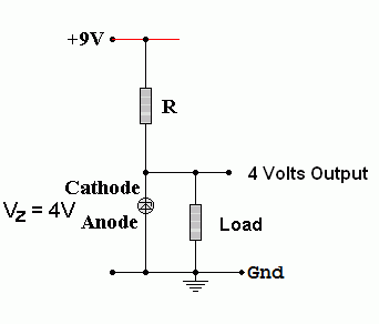
If the Zener voltage is 4V and the supply voltage is 9V, the potential difference across R will be 5V.
Using Ohm's Law ...
To calculate the Zener diode power rating ...
Power_Rating = (Maximum_Load_Current + Minimum_Zener_Current) x Zener_Breakdown_Voltage
P = (95 x 10-3 + 5 x 10-3) x 4
P = 400mW or 0.4W
ePower = I V Power = I2 R Power = V2 / R
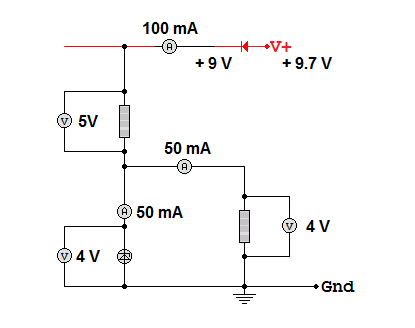
This diagram shows a Zener diode operating under typical conditions. In exam questions, the diode is often operating under it's extreme conditions with either zero or maximum load current. In all cases, the total circuit current is the same.

Load Power
Use the load voltage and the load current.
P = I V P = 0.05 x 4 P = 0.2 Watts
Resistor Power
Use the resistor voltage and the resistor current.
P = I V P = 0.1 x 5 P = 0.5 Watts
Zener Diode Power
Use the Zener diode voltage and the Zener diode current.
P = I V P = 0.05 x 4 P = 0.2 Watts
Whole Circuit Power
Use the whole circuit voltage and the whole circuit current.
P = I V P = 0.1 x 9 P = 0.9 Watts
Notice how all the separate component powers add up to the whole circuit power.
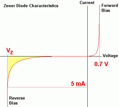
fThe graph below shows the current/voltage characteristics of a Zener diode. The reverse leakage current has been exaggerated to make it show on the graph. The reverse breakdown voltage varies between different Zener diodes. The range of values goes from a few Volts up to about 200 Volts.

If the reverse bias current is less than about 5mA, the Zener voltage will be lower than the expected value. When designing circuits to give a reference voltage using a Zener diode, the minimum Zener current should always be at least 5 mA (check the data sheet). The yellow region in the graph shows where the Zener voltage is not properly established.
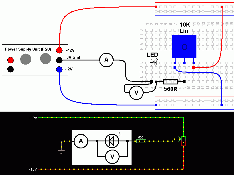
gThis circuit can be used to test the behaviour of any low voltage / low current diode. These include typical silicon diodes such as the 1N4001, LEDs and Zener diodes. The activity below shows an LED.
Build this circuit and measure and record the potential difference across the diode and the current through it. Repeat these measurements for the full range of movement of the potentiometer. Plot a graph of your results. Plot your graph as you go and get sufficient readings before you dismantle your circuit.

Your tasks ...
Make sure there are no gaps in your graph where extra measurements should have been taken.
hFor the Falstad Circuit Simulation, CTRL+Click 4 Volt Zener Diode
In options, check European Resistors and uncheck Conventional Current.
Adjust the Potentiometer
Alternatively view Diodes_Zener.txt.
Save or copy the text on the web page. Import the saved or copied text into the Falstad simulator.
Here is the new HTML5 Simulator Site.
reviseOmatic V3 Contacts, ©, Cookies, Data Protection and Disclaimers Hosted at linode.com, London