RANDOM PAGE
SITE SEARCH
LOG
IN
SIGN UP
HELP
To gain access to revision questions, please sign up and log in.
Non-Exam Extras
Amplitude Modulation 40kHz Transmitter
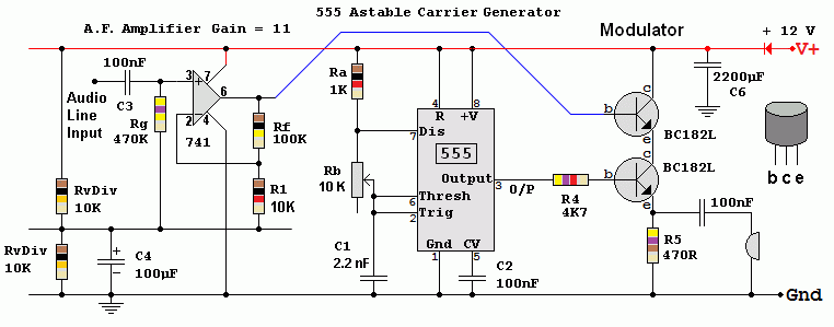
- The audio amplifier boosts the signal from the computer sound card. It has a gain of 11.
- The astable oscillates at 40kHz.
- The audio output from the operational amplifier is centered on 6 Volts, rising above and falling below this level.
- This audio signal controls the top emitter follower.
- The output from the astable oscillator is fed to the second emitter follower in series with the first.
- The audio signal modulates the size of the square wave signal fed to the ultrasound transducer and AM is produced.
- Noise free reception was obtained 4 metres from the transmitter. This suggests that a much larger range might be possible with careful setup of the transmitter and receiver.
- Much greater ranges can be obtained with parabolic dish reflectors. See if you can get a couple of surplus Sky dishes from freecycle.
- Multiple transducers could be used to produce a more directional beam, both at the transmitter and receiver.
- Music and voice transmissions were very muffled because the bandwidth of the 40kHz transducers was much too narrow.
- BPSK31 data transmissions worked very well. We used Digital Master 780 which is part of the Ham Radio Deluxe suite. This interesting PC software uses a computer sound card to send and receive the data. Sadly this software now costs money. Before it was funded by donation so students could try it out for free.

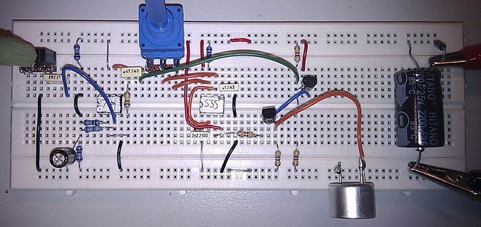
The photo differs very slightly from the circuit diagram.
- The top emitter follower does not need a voltage divider and coupling capacitor as the op-amp output is already at the correct level.
- The coupling capacitor to the ultrasound transducer is optional.

reviseOmatic V3
Contacts, ©, Cookies, Data Protection and Disclaimers
Hosted at linode.com, London


