RANDOM PAGE
SITE SEARCH
LOG
IN
SIGN UP
HELP
To gain access to revision questions, please sign up and log in.
Non-Exam Extras
A Transmitter Using Heterodyne Methods with a Mixer
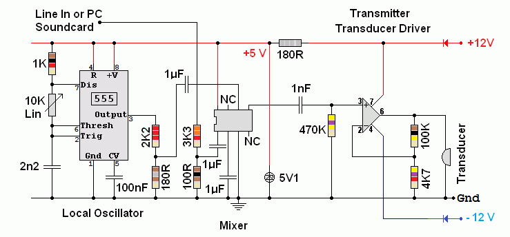
Proposed System Diagram
With the narrow bandwidth of the ultrasound transducer at 40 +/- 1 kHz, only one of the two sidebands will be transmitted strongly.

This Circuit Has Been Tested - See Comments Below

A student has now built a DSB transmitter based on this circuit.
- The 741 chip driving the transducer does not have sufficient gain bandwidth product.
- The 741 chip works but it provides less output than expected.
- Using an RC5534N op amp with about ten times the gain bandwidth product solved that problem.
The LM386 Audio amp could also be used with a gain of 20.
- A transducer driver gain of 22 seems to be sufficient: Rf = 100K and R1 = 4K7.
- The local oscillator and computer sound card attenuators seem to be about right giving a mixer output of just under 200mV. Higher drive levels might also work but this was not tried.
- Replacing the 555 astable with a sine wave oscillator might reduce the spurious signals in the output but these signals are mostly at the third harmonic of 40kHz (120kHz) and at the higher odd harmonics. This is far outside the pass-band of the ultrasound transducers so these signals don't seem to matter.
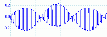
PSK31: The Mixer Output - The Y axis in in Volts - The X axis shows 40kHz.

The BPSK31 PC software was downloaded here. The Digital Master 780 program within the Ham Radio Deluxe suite was used. This used to be funded by donation. Now it costs $100. You can get a 30 day trial though.
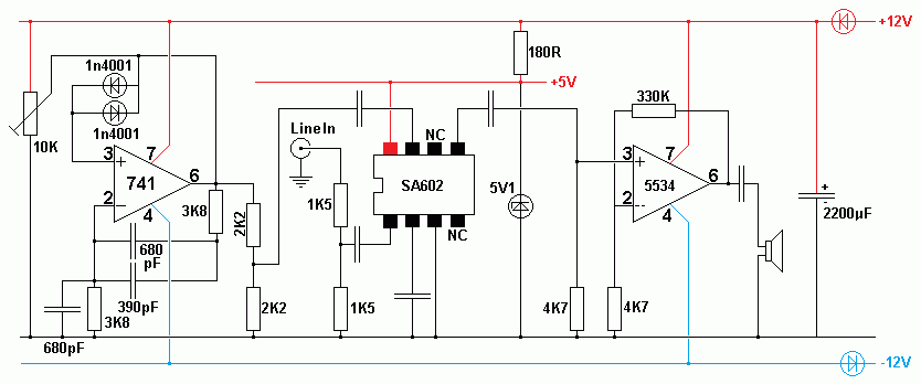
Mark 2 Circuit
- Sine wave oscillator on 39 or 41 kHz.
- Line input suitable for connection to a computer sound card line out.
- SA602 Mixer similar to the one above.
- Faster op amp driver.

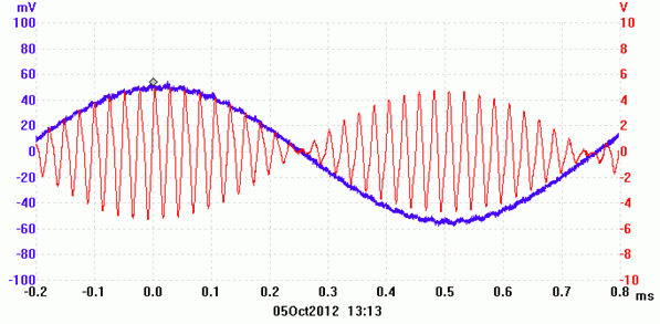
BPSK31 Transmitter Output - Note the Phase Reversal

reviseOmatic V3
Contacts, ©, Cookies, Data Protection and Disclaimers
Hosted at linode.com, London


