WANTED: Individual or team to take over this project. I'm in my 70's and want to put my feet up. Contact details in footer.
| GCSE Sequential Logic BCD Counting D Type Flip Flop D Type Latch >Decade Counter< Sequencer Up Counter |
Sequential Logic Decade Counter |
|
On the rising edge of the clock pulse, the next output goes high (moving left to right in the diagram below).
At any time, only ONE output is high.
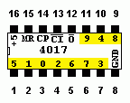 Data Sheet from Texas Instruments
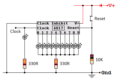
View this circuit in the Lushprojects Simulator. The simulation differs from real life because an extra NOT gate is needed.
Here is the correct circuit diagram for the 4017 chip without the NOT gate.
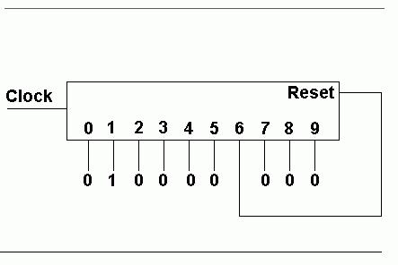
This counter will count to five. When it hits six, the reset pin goes high and microseconds later the counter has reset. The reset is so fast that no human could ever see it reaching six.
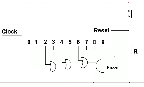
As this counter goes from 0 to 9, the buzzer will sound when it reaches 0, 2, 4 and 6. This will give four beeps with a short pause before repeating.
If the reset switch is held down, the counter will reset to zero. Pin 0 will be high so the buzzer will sound as long as the reset switch is held down.
The diodes act as OR Gates. If pin 9 is high, following the wires with doides, the left amber light will be shining and the right hand red and amber lights also.

Real world traffic lights are bright and need much more current than this chip can provide. MOSFET switch driver circuits can be placed between the counter chip and the traffic lights.
Subject Name Level Topic Name Question Heading First Name Last Name Class ID User ID
|
Q: qNum of last_q Q ID: Question ID Score: num correct/num attempts Date Done
|
Question Text
image url
Help Link
Add Delete Clone Edit Hardness
Contact, Copyright, Cookies and Legalities: C Neil Bauers - reviseOmatic V4 - © 2016 to 2026
Hosted at Akamai Cloud - London
Please report website problems to Neil