WANTED: Individual or team to take over this project. I'm in my 70's and want to put my feet up. Contact details in footer.
| A Level Signal ADC Flash ADC Ramp DAC Summing Distortion Problems Regenerator Sample and Hold Sampling >Serial and Parallel< signal to noise ratio |
Signal Serial and Parallel |
|
Parallel data connections used to be quite common outside the computer case. The parallel cables had at least 8 wires, 25 in printer cables and many more for connections to external hard disks. The data bits were carried side by side on the many cables. This greatly increased the amount of data that could be carried compared with similar serial connections. More recently, serial connections have become so fast that the extra cost and complexity of parallel connections has made then non cost effective.
Parallel dats buses are still common inside the computer case or phone or tablet. Here the need for speed is so great that parallel connections remain worthwhile.
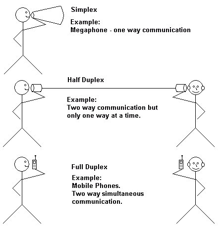
The data is sent along a single wire with an earth wire (sometimes the actual earth). Pulses are sent down the line one after another. This link only works in one direction at a time. This is called Half Duplex. For Full Duplex, two wires are needed, one for each direction plus the earth wire.
This dates back to the telegraph. Morse code messages were sent between towns and cities. Then mechanical machines sent and received text using binary codes to represent the characters. Later computers used the same signalling methods. Most recently USB, FireWire and SATA connections have become common.
One way communication including megaphones and broadcast radio and TV. The programmes are transmitted but no one can reply. Internet multicasts are one way simplex links. One simplex transmission uses one frequency or channel. Simplex transmissions can be to single or multiple recipients.
Two way traffic but not at the same time. Walkie talkies can transmit or receive but never at the same time. Contraflow roadworks are also like half duplex. Traffic flows both ways but never at the same time. Half Duplex transmissions use one frequency or channel for either transmitting or receiving.
Simultaneous two way communication. Mobile phones and many types of computer data links such as newer fully switched Ethernet networks. This is achieved by using separate frequencies or media for transmission and reception. Alternatively it can be achieved using time division multiplexing on a single channel, switching at high speed between transmit and receive.

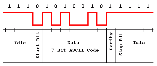
A single data carrying wire is used. To transmit lots of bits, they have to be sent one at a time. This technology was invented back in the days of mechanical Teletype machines so start and stop bits were needed.
Because the original serial communication systems were mechanical, time had to be allowed for the machinery to start up and shut down. This problem was solved by sending one or more start bits to allow the machine to start up. Then the data was sent. Finally one or more stop bits would be sent to allow the machine to shut down again. Modern digital systems don't need this start and stop time so although start and stop bits are still part of the serial communications standard, the channel is configured with zero start and stop bits. The start bit also allows the receiver to synchronise itself with the sender.
A method was needed to detect transmission errors. To achieve this, an extra bit was transmitted called the parity bit. When using even parity, this bit was set to ensure that an even number of ones was transmitted for each text character sent. If the receiver picked up an odd number of ones, an error had been detected. Sometimes odd parity was used. This is the identical concept but the receiver would expect error free data to contain an odd number of ones.
Modern packet switched networks employ improved versions of parity error detection using mathematical techniques like header checksums.
One start bit, Seven data bits, Even parity, One stop bit
In binary, the seven bit ASCII code for "R" is 1010010. For even parity, the parity bit must be one because the data contains three ones (an odd number). One start bit is needed and also one stop bit. When the line is idle, a one is transmitted.

The simple explanation
Both are measured in bits per second. Baud rate is named after Émile Baudot.
In the example above, seven useful data bits have been transmitted but ten bits need to be sent to achieve this.
This is the number of data bits transmitted per second (seven in this example).
This is the total number of bits including start, stop and parity sent per second (ten in this example). Normal serial lines have a lower bit rate than baud rate.
If the line is configured with zero start bits, zero stop bits and no parity, the bit and baud rated are equal because no extra control bits are being sent.
Using QAM8, three bits are transferred per baud or symbol. Wikipedia has more information on this complex topic.
All devices use the same clock signal.
The internal workings of computers, PICs and Microcontrollers are controlled and synchronised with a single clock signal. Data links between these devices also use this clock signal. This is known as Synchronous Communication. Some data links across long distances also use clock signals and both ends of the link are synchronised to the same clock.
Each device uses its own clock signal.
Other methods are needed to handle transferred data. For example you can't control when keys on a keyboard are pressed or when data packets will arrive from the internet. Serial communications described here are asynchronous and start and stop bits are needed. The start bit allows the receiving device preparation time ready for the incoming data. The bursts of data are short otherwise the receiver's clock might go out of step with the sender's clock.
For interconnecting portable devices, serial links are nearly always preferred for their lower cost and simplicity. Also speeds have improved so much that there are few disadvantages, even for high speed applications like disk access.
Parallel links are still preferred within the computer for shifting huge amounts of data as quickly as possible.
Subject Name Level Topic Name Question Heading First Name Last Name Class ID User ID
|
Q: qNum of last_q Q ID: Question ID Score: num correct/num attempts Date Done
|
Question Text
image url
Help Link
Add Delete Clone Edit Hardness
Contact, Copyright, Cookies and Legalities: C Neil Bauers - reviseOmatic V4 - © 2016 to 2026
Hosted at Akamai Cloud - London
Please report website problems to Neil